118 The PQF-Manager user interface Manual Power Quality Filter PQFM
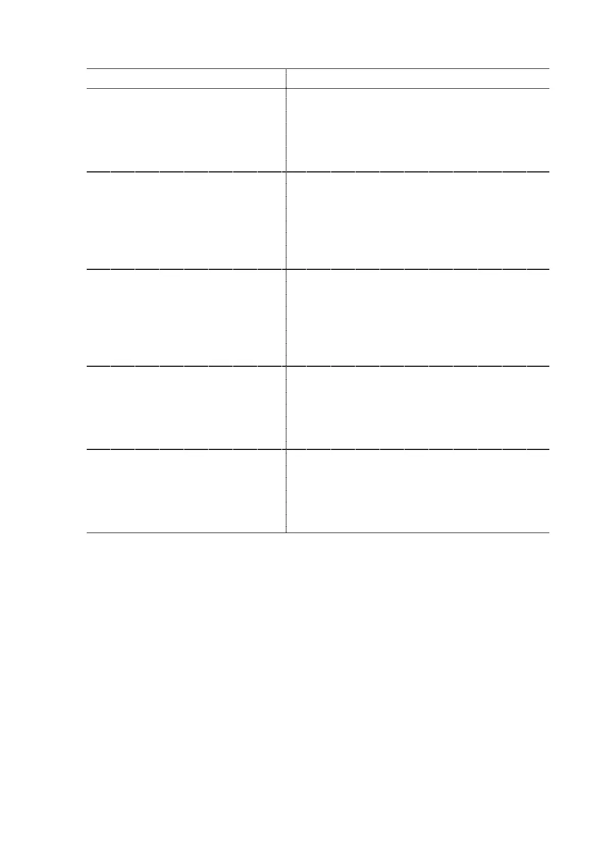
Table 47: Reactive power tasks that the filter can perform
Reactive power task requirement
Description and filter set
Balance load
: Disabled
The filter will not do any reactive power task,
regardless of the values set for cos ϕ or static
reactive power
Power factor compensation with
inductive power factor set point, no
load balancing required
(a)
Target cos ϕ: Desired power factor between 0.6 and
1.0
The filter will do power factor compensation up to
the cosϕ set point, regardless of the value set for
static reactive power(b)
Power factor compensation with
capacitive power factor set point, no
load balancing required
(a)
Target cos ϕ
: Desired power factor between 0.6 and
1.0
The filter will do power factor compensation up to
the cosϕ set point, regardless of the value set for
static reactive power
©
Fixed capacitive power step with a
rating of x kvar, no load balancing
required
(a)
Q static
: x kvar
The filter will generate x kvar reactive capacitive
power, regardless of the value set for the target cos
ϕ
Fixed inductive power step with a
rating of x kvar, no load balancing
required
(a)
Q static
: x kvar
The filter will absorb x kvar reactive inductive
power, regardless of the value set for the target cos
ϕ
Remarks:
(a)
When load balancing is required, set the ‘
Balance load
’ flag to the desired mode. The
following modes are available depending on the way the filter is connected (3-W or 4-W)
- ‘Disabled’: No load balancing is done.
- ‘L-L’: Loads connected between phases only are balanced. Loads connected between
phases and neutral are not balanced.
- ‘L-N’: Loads connected between phase and neutral are balanced. Loads connected
between phases are not balanced. This mode is only available when the filter is connected
in 4-W mode.
- ‘L-L & L-N’: Both loads connected between phase and neutral as well as loads connected
between phases are balanced. This mode is only available when the filter is connected in
4-W mode.
Note: The modes ‘L-N’ and ‘L-L & L-N’ can be used to minimize the amount of fundamental
frequency current flowing in the neutral.
(b)
If the measured cos ϕ is higher than the set point and is inductive (e.g. measured 0.97
inductive and set point 0.92 inductive, then the filter will not make any correction. If the
measured cos ϕ is capacitive, the filter will correct the power factor to 1.0