Manual Power Quality Filter PQFM Technical specifications 225
trafo
Transformer nominal power
z
trafo
: Transformer impedance in %
z
load
: Impedance between notch producing load
and filter connection point (% in load base)
Maximum 2% of phase to phase voltage
Surge withstand capability with
optional surge arrester
(Voltage group V1)
(Voltage group V2)
600V for cULus version
Auxiliary circuit voltage (internally
derived)
Neutral connection systems
Environment class (according to
IEC 60439-1) (CE version only)
General construction aspects
EMC immunity (CE version only)
EMC emissions (CE version only)
RMS output current per power unit type (50Hz or 6
(Voltage group V1)
Unit type 1 (M07, S07): 70 A
Unit type 2 (M10, S10): 100 A
Unit type 3 (M13, S13): 130 A
Unit type 4 (M15, S15): 150 A
480 V < Ue ≤ 690 V (Voltage group V2),
CE version
480 V ≤ Ue ≤ 600 V (Voltage group V2),
cULus version
Unit type 1 (M10, S10): 100 A
Up to 8 power units/filter (possible to use different power
unit ratings of the same voltage group but difference
between smallest and biggest unit should maximum be
one current category.)
The units (master, slave) must have PQF-Manager
firmware version 2.11.ro or higher.
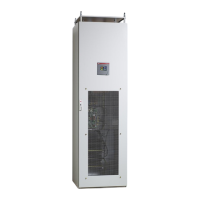
One power unit per cubicle.
For full redundancy combine master units of same rating.
If any unit in a master-master filter system fails, the other
units can keep running.


 To Next Page