107
FEM630 | ELECTROMAGNETIC FLOWMETER | OI/FEM630-EN REV. A
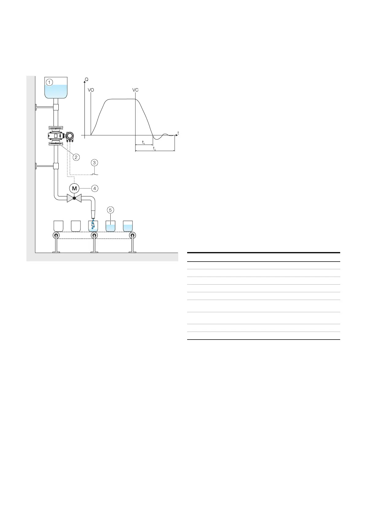
8 ...Operation
Filling function
Menu / parameter Description
Mode Pulse
Outp. Flow Direction Forward
Input/Output / ...Setup Pulse Output
Output Value Pulse Pulse Volume Flow
Pulses per Unit
Setting in accordance with
requirement
Pulse Width
Setting in accordance with
requirement
Mode
Supply tank
Sensor
Start / stop fill operation (digital input through plug-in card)
Fill valve
Filling tank
Valve open (filling started)
Valve closed (fill quantity reached)
Valve closing time
Overrun time
1
2
3
4
5
VO
VC
t1
t2
Figure 69 FillMass fill function
The optional filling function allows filling with filling times> 3
seconds.
Filling quantity is configurable and the filling process can be
started via the digital input (plug-in card).
As soon as the filling quantity has been reached, the valve can
be closed via the digital output. Filling quantity correction is
calculated by measuring the overrun quantity. Additionally,
the low flow cut-off can be configured if required.
Setup
For the configuration of the fill function, the following steps
must be performed:
1 The fill function must be active. See also the ‘Device
Setup / ...Transmitter / ...Feature Settings / ...’ menu.
2 One digital output must be configured as a binary output
with the function ‘Batch End Contact’. See also the
‘Input/Output / ...’ menu. As an option, one digital input
(option module) can be configured with the function
‘Start/Stop Batching’ at the start of the filling process.
3 The parameters for the fill function must be configured.
See also the ‘Totalizer / ...Batching / ...’ menu.
Note
During fast filling processes, the damping should be set to
the minimum value to guarantee the greatest possible
accuracy of the fill quantity.
See also the ‘Device Setup / ...Transmitter / ...’ menu.
Brief overview of configurations
Configuration of digital output 41 / 42 as pulse output for
forward flow and digital output 51 / 52 as pulse output for
reverse flow.