41
FEM630 | ELECTROMAGNETIC FLOWMETER | OI/FEM630-EN REV. A
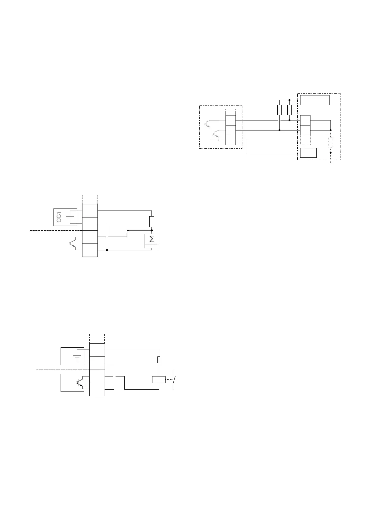
Connection examples
Input and output functions are configured via the device
software in accordance with the desired application.
Parameter descriptions on page 77.
Active digital output 41 / 42, 51 / 52, V3 / V4
When the ‘loop power supply 24 V DC (blue)’ plug-in card is
used, the digital outputs on the basic device and on the
option modules can also be wired as active digital outputs.
Note
Each ‘loop power supply (blue)’ plug-in card must only power
one output.
It must not be connected to two outputs (for example digital
output 41 / 42 and 51 / 52)!
Digital output 41 / 42, 51 / 52 passive on distributed
control system
The connection example shows usage for digital output 41 /
42; the same applies to usage for digital output 51 / 52.
optoelectronic coupler of the digital outputs in the
transmitter.
The input on the distributed control system is reduced from
24 V DC to 0 V DC (falling edge) with ‘1’ at the digital output.
6 ...Electrical connections
...Pin assignment
G11744-01
A
V2-
V1+
IE
+24 V, max. 25 mADC
0V
41+
42/52
B
OC1
012345
R
B
‘Loop power supply (blue)’ plug-in card in slot 1
Digital output, digital output 41 / 42
Transmitter
Distributed control
system / Memory
programmable controller
Ex. 1 Input 1
Ex. 2 Input 2
R
Resistor for current
limitation
R
I
Distributed control
system internal
resistance
‘Loop power supply (blue)’ plug-in card in slot 1
‘Digital output (green)’ plug-in card in slot 2
A
B
A
B
A
B
Figure 48 Active digital output 41 / 42 (example)
Figure 49 Active digital output V3 / V4 (example)
Figure 50 Digital output 41 / 42 on
distributed control system (example)
G11913
A
V2-
V1+
IE
+24 V, max. 25 mADC
0V
B
R
B
V4-
V3+
OC2
OC1
G12366
A
Ex.1
Ex.2
0 V DC
16 ... 30VDC
B
Rx
Rx
41+
51+
IE
42-/
52-
Ri