36
FEM630 | ELECTROMAGNETIC FLOWMETER | OI/FEM630-EN REV. A
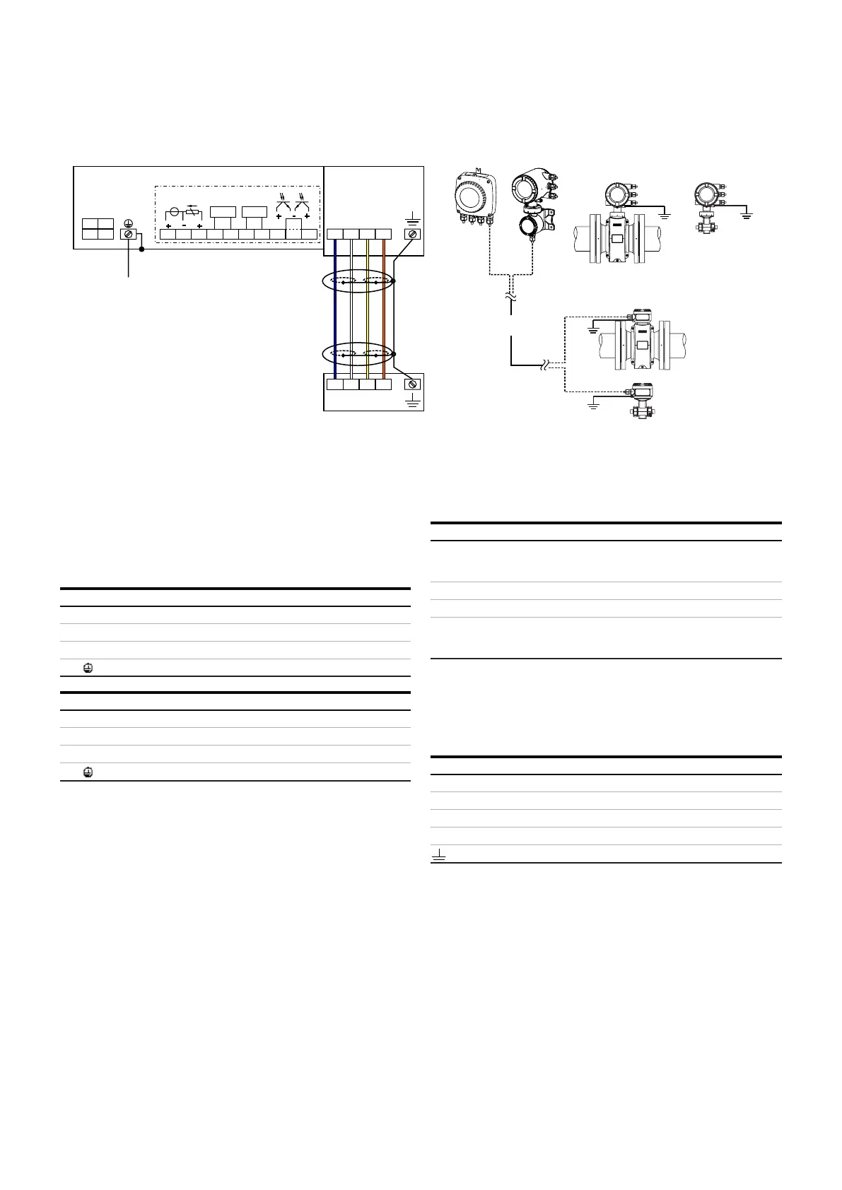
6 ...Electrical connections
Pin assignment
G12153
A
LN
1+ 2-
PE
B
GND
AB
+
-
+
-
+
HART
Uco
32 31
V3
V4 V1 V2
41
52
42
51
+
Oc2 Oc1
AB
UFE
GND
UFE
B
≤ 200 m
( 656 ft)≤
Connections for power supply and inputs / outputs
Connections for signal cable (remote mount design only)
A
B
Figure 38 Electrical connections
Note
For additional information on the grounding of the
transmitter, see Grounding on page 17.
Connections for the power supply
Connecting the signal cable
Only for remote mount design.
The sensor housing and transmitter housing must be
connected to potential equalization.
Connections for inputs and outputs
AC power supply
Terminal
Function / comments
L
Phase
N
Neutral conductor
PE /
Protective earth (PE)
DC power supply
Terminal
Function / comments
+
-
PE /
Protective earth (PE)
Terminal Function / comments
or
For details, see Optional plug-in cards
Terminal Function / comments
U
FE
Sensor power supply
GND Ground
A Data line
B Data line
Functional earth / Shielding