37
FEM630 | ELECTROMAGNETIC FLOWMETER | OI/FEM630-EN REV. A
6 ...Electrical connections
...Pin assignment
Electrical data for inputs and outputs
Note
• An additional document with Ex safety instructions is
available for measuring systems that are used in
potentially explosive atmospheres.
• Ex safety instructions are an integral part of this manual.
As a result, it is crucial that the installation guidelines and
connection values it lists are also observed. The icon on
the name plate indicates the following:
Current output Uco / 32, 31 / 32
Can be configured for outputting mass flow and volume
flow via the on-site software.
Power supply
*Source voltage U depends on the load R
B
and must be within the
permissible range.
For information on communication via the HART protocol,
refer to HART® communication on page 48.
AC power supply
Terminals
L / N
Operating voltage
Power consumption
S
Power-up current
DC voltage supply
Terminals
Operating voltage
Ripple
Power consumption
Power-up current
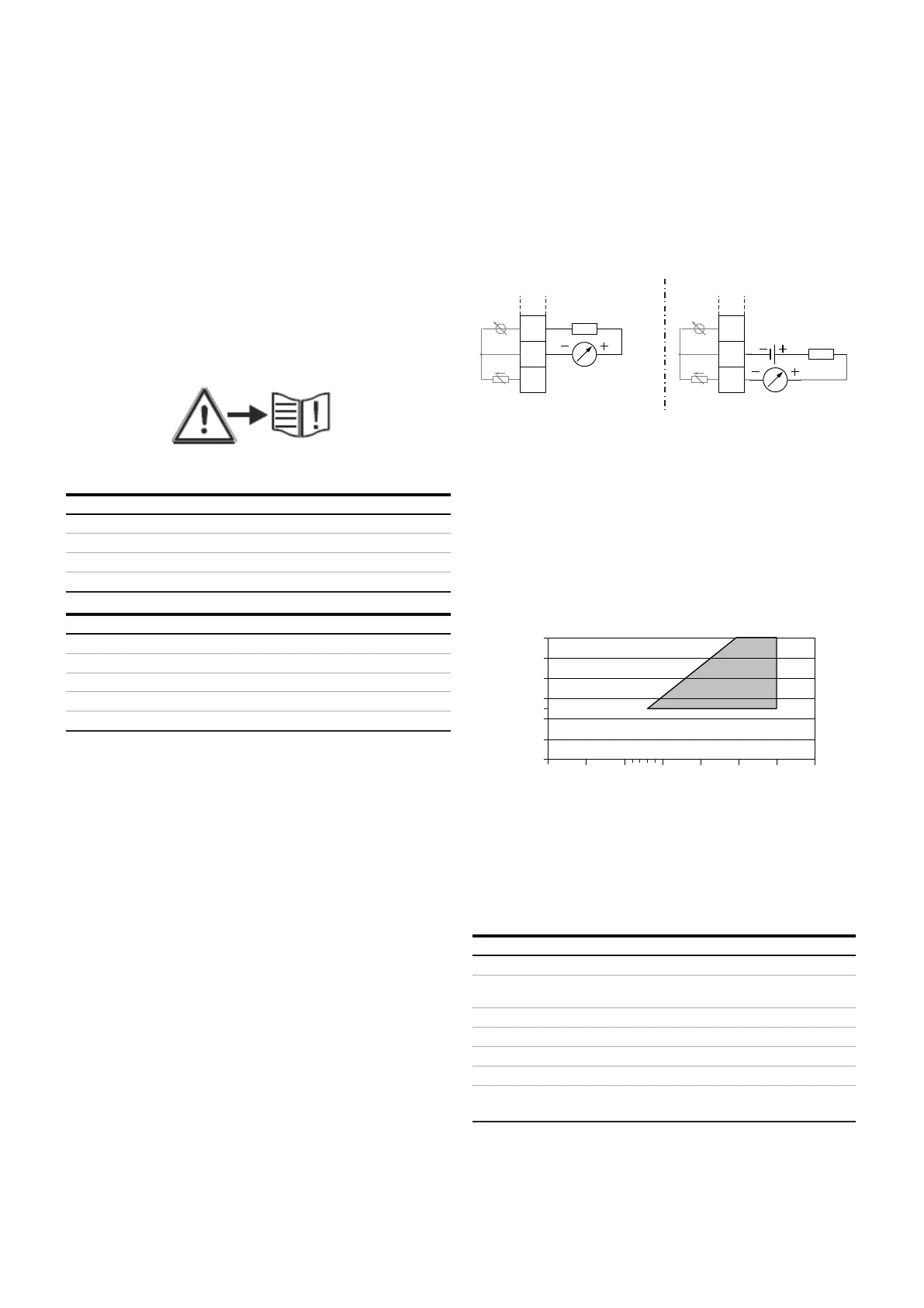
Current output Active Passive
Terminals
Output signal
Load RB
Source voltage U*
—
Measuring error
Resolution
Insulation
The current output and digital outputs are electrically
isolated.
Current output Uco / 32, active
Current output 31 / 32, passive
Permissible source voltage U
q
for passive outputs in relation to load
resistance R
B
where I
max
= 22 mA. (unreadable type) = Permissible range
A
B
Figure 39
B
Figure 40 Source voltage for passive outputs
G11596-02
+
-
IE
32-
Uco
32-
IE
31+
R
B
R
B
Uq
31+
Uco
+
-
G10323-02
0
0
100
200
300
400
500
600
5101520253035