ANSI05000164 V1 EN-US
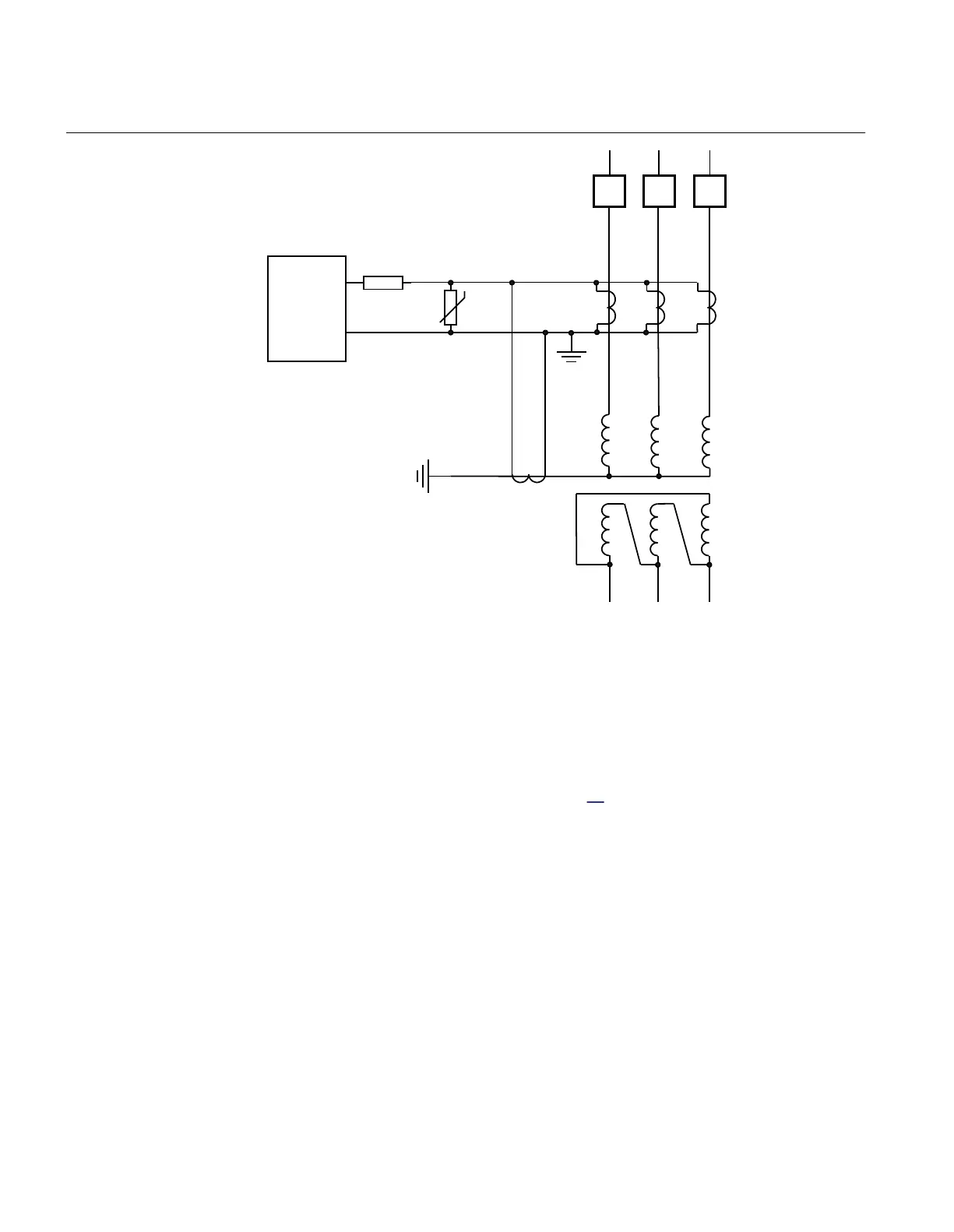
Figure 48: Example for the high impedance restricted earth fault protection
application
For a through fault one current transformer might saturate when the other CTs still will
feed current. For such a case a voltage will be developed across the measuring branch.
The calculations are made with the worst situations in mind and a minimum operating
voltage V
R
is calculated according to equation
13
EQUATION1531-ANSI V1 EN-US (Equation 13)
where:
IF
max is the maximum through fault current at the secondary side of the CT
Rct
is the current transformer secondary winding resistance and
Rl
is the maximum loop resistance of the circuit at any CT.
Section 7 1MRK 511 401-UUS A
Differential protection
130 Bay control REC670 2.2 ANSI
Application manual

 Loading...


