The residual current, out on the line, is calculated at an operational case with minimal
ground-fault current. The requirement that the whole line shall be covered by step 2
can be formulated according to equation 42.
step2 0I 0.7 3I (at remote busbar)³ ×
EQUATION1202 V4 EN-US (Equation 42)
To assure selectivity the current setting must be chosen so that step 2 does not operate
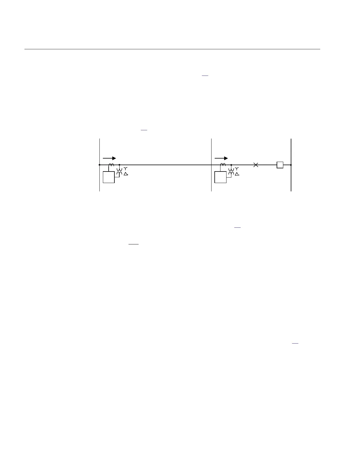
at step 2 for faults on the next line from the remote substation. Consider a fault as
shown in Figure 75.
One phase-ground-fault
67N
50/51N
50/51N
67N
ANSI05000155 V2 EN-US
Figure 75: Step 2, selectivity calculation
A second criterion for step 2 is according to equation
43.
1
1
0
step2 step1
0
3I
I .2 I
3I
³ × ×
EQUATION1203 V4 EN-US (Equation 43)
where:
I
step1
is the current setting for step 1 on the faulted line.
Step 3
M15282-164 v6
This step has directional function and a time delay slightly lar
ger than step 2, often 0.8
s. Step 3 shall enable selective trip of ground faults having higher fault resistance to
ground, compared to step 2. The requirement on step 3 is selectivity to other ground-
fault protections in the network. One criterion for setting is shown in Figure 76.
Section 8 1MRK 511 401-UUS A
Current protection
182 Bay control REC670 2.2 ANSI
Application manual

 Loading...


