Line voltage drop
SEMOD159053-105 v6
The purpose with the line voltage drop compensation is to control the voltage, not at
the power transformer low voltage side, but at a point closer to the load point.
Figure 172 shows the vector diagram for a line modelled as a series impedance with
the voltage V
B
at the L
V busbar and voltage V
L
at the load center. The load current on
the line is I
L
, the line resistance and reactance from the station busbar to the load point
are R
L
and X
L
. The angle between the busbar voltage and the current, is j. If all these
parameters are known V
L
can be obtained by simple vector calculation.
Values for R
L
and X
L
are given as settings in primary system ohms. If more than one
line is connected to the LV busbar, an equivalent impedance should be calculated and
given as a parameter setting.
The line voltage drop compensation function can be turned Enabled/Disabled by the
setting parameter OperationLDC. When it is enabled, the voltage V
L
will be used by
the Automatic voltage control for tap changer function, TR1ATCC (90) for single
control and TR8ATCC (90) for parallel control for voltage regulation instead of V
B
.
However, TR1ATCC (90) or TR8ATCC (90) will still perform the following two
checks:
1. The magnitude of the measured busbar voltageV
B
, shall be within the security
range, (setting Vmin and Vmax). If the busbar voltage falls-out of this range the
line voltage drop compensation calculations will be temporarily stopped until the
voltage V
B
comes back within the range.
2. The magnitude of the calculated voltage V
L
at the load point, can be limited such
that it is only allowed to be equal to or smaller than the magnitude of V
B
,
otherwise V
B
will be used. However, a situation where V
L
>V
B
can be caused by a
capacitive load condition, and if the wish is to allow for a situation like that, the
limitation can be removed by setting the parameter OperCapaLDC to Enabled.
1MRK 511 401-UUS A Section 14
Control
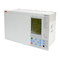
Bay control REC670 2.2 ANSI 415
Application manual
 Loading...
