EQUATION1848 V2 EN-US (Equation 117)
Where:
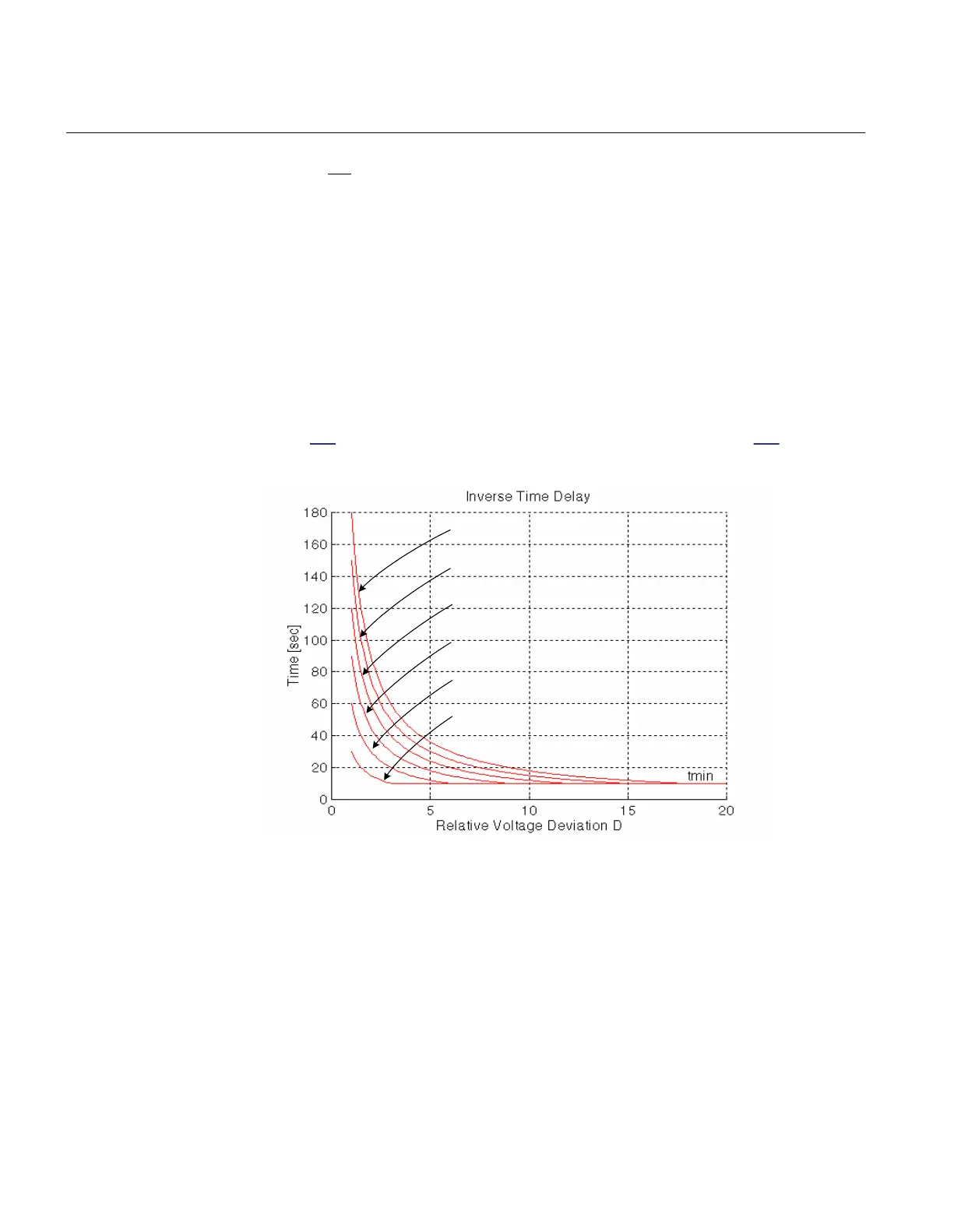
DA absolute voltage deviation from the set point
D relative voltage deviation in respect to set deadband value
For the last equation, the condition t1 > tMin shall also be fulfilled. This practically
means that tMin will be equal to the set t1 value when absolute voltage deviation DA is
equal to ΔV ( relative voltage deviation D is equal to 1). For other values see
figure
171. It should be noted that operating times, shown in the figure 171 are for 30,
60, 90, 120, 150 & 180 seconds settings for t1 and 10 seconds for tMin.
t1=180
t1=150
t1=120
t1=90
t1=60
t1=30
IEC06000488_2_en.vsd
IEC06000488 V2 EN-US
Figure 171: Inverse time characteristic for TR1ATCC (90) and TR8ATCC (90)
The second time delay, t2, will be used for consecutive commands (commands in the
same direction as the first command). It can have a definite or inverse time
characteristic according to the setting t2Use (Constant/Inverse). Inverse time
characteristic for the second time delay follows the similar formulas as for the first
time delay, but the t2 setting is used instead of t1.
Section 14 1MRK 511 401-UUS A
Control
414 Bay control REC670 2.2 ANSI
Application manual

 Loading...


