Usually the tap changer mechanism can give a signal, “Tap change in progress”, during
the time that it is carrying through an operation. This signal from the tap changer
mechanism can be connected via a BIM module to TCMYL
TC (84) or TCLYLTC (84)
input TCINPROG, and it can then be used by TCMYLTC (84) or TCLYLTC (84)
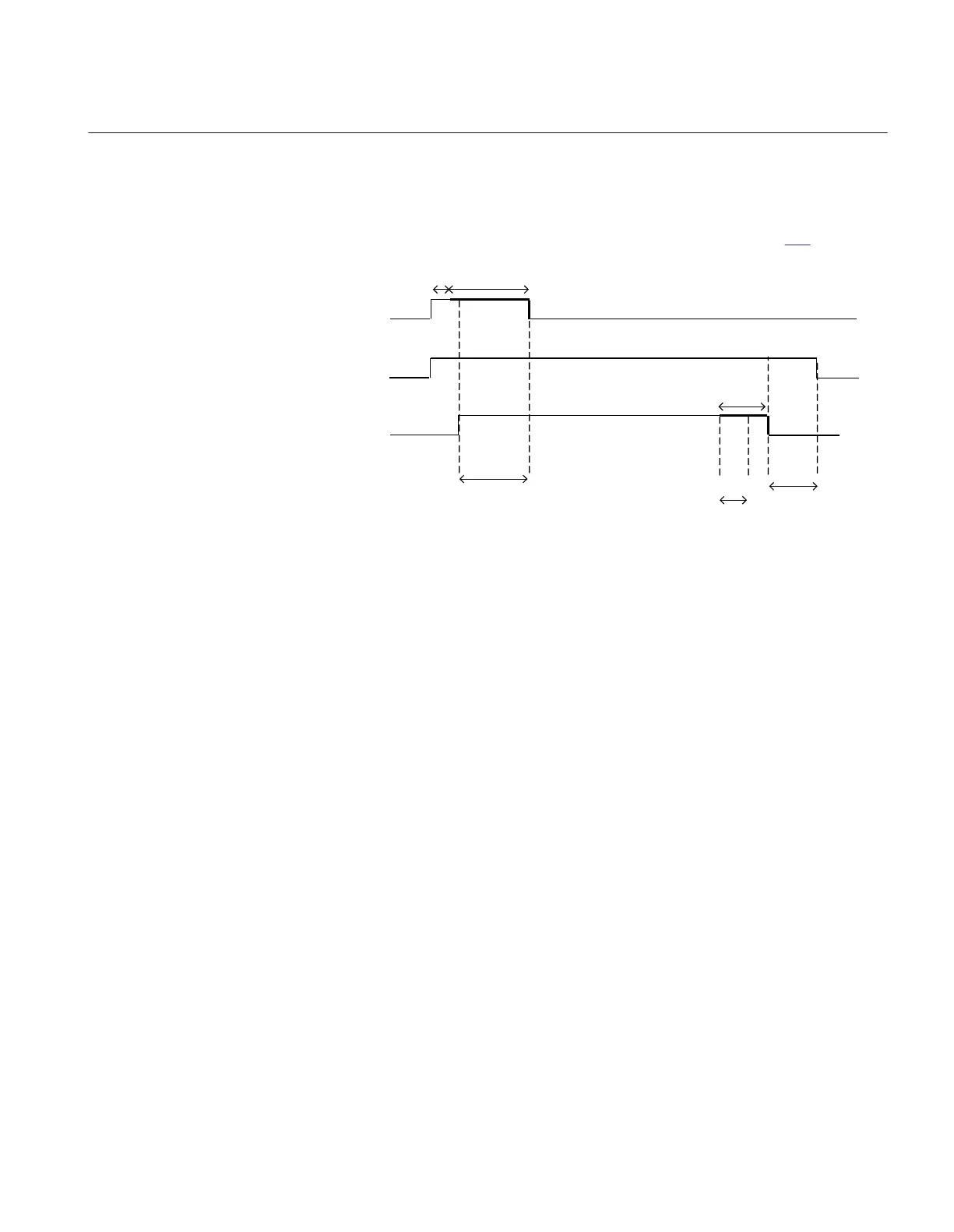
function in three ways, which is explained below with the help of figure
180.
VRAISE/VLOWER
tTCTimeout
TCINPROG
a
h
d
e f
g
cb
en06000482_ansi.vsd
ANSI06000482 V1 EN-US
Figure 180: Timing of pulses for tap changer operation monitoring
pos Description
a Safety margin to avoid that TCINPROG is not set high without the simultaneous presence of an
VRAISE or VLOWER command.
b Time setting
tPulseDur
.
c Fixed extension 4 sec. of
tPulseDur
, made internally in TCMYLTC (84) or TCLYLTC (84) function.
d Time setting
tStable
e New tap position reached, making the signal “tap change in progress” disappear from the tap
changer, and a new position reported.
f The new tap position available in TCMYLTC (84) or TCLYLTC (84).
g Fixed extension 2 sec. of TCINPROG, made internally in TCMYLTC (84) or TCLYLTC (84) function.
h Safety margin to avoid that TCINPROG extends beyond
tTCTimeout
.
The first use is to reset the Automatic voltage control for tap changer function
TR1A
TCC (90) for single control and
TR8ATCC (90) for parallel control as soon as
the signal TCINPROG disappears. If the TCINPROG signal is not fed back from the
tap changer mechanism, TR1ATCC (90) or TR8ATCC (90) will not reset until
tTCTimeout has timed out. The advantage with monitoring the TCINPROG signal in
this case is thus that resetting of TR1ATCC (90) or TR8ATCC (90) can sometimes be
made faster, which in turn makes the system ready for consecutive commands in a
shorter time.
1MRK 511 401-UUS A Section 14
Control
Bay control REC670 2.2 ANSI 441
Application manual

 Loading...


