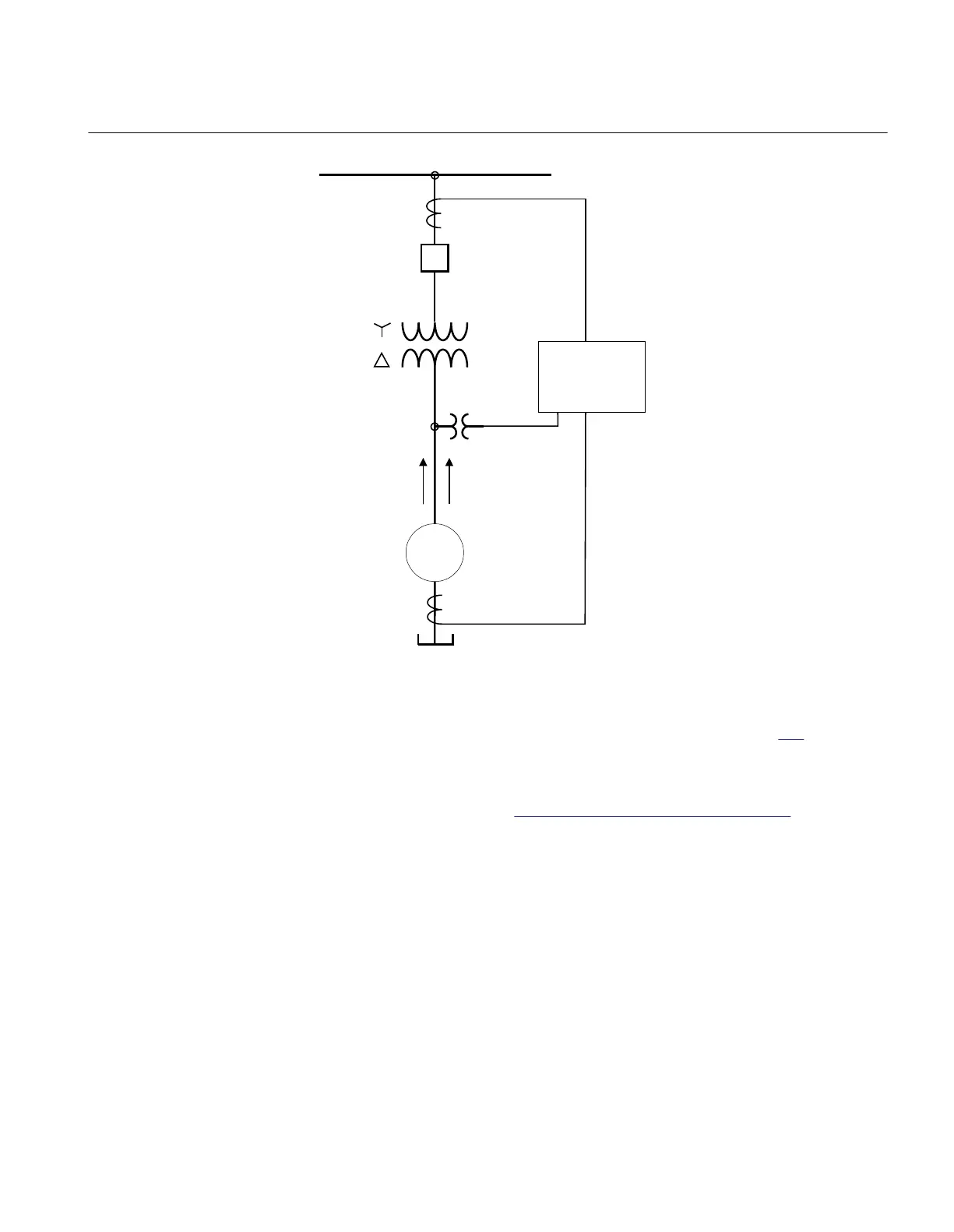
230kV Busbar
300/5
4000/5
100 MVA
G
P Q
100 MVA
15.65kV
ANSI09000041-1-en.vsd
15/0.12kV
V
AB ,
V
BC
,
IED
ANSI09000041 V1 EN-US
Figure 209: Single line diagram for generator application
In order to measure the active and reactive power as indicated in figure
209, it is
necessary to do the following:
1. Set correctly all CT and VT data and phase angle reference channel
PhaseAngleRef (see Section “Setting of the phase reference channel”) using
PCM600 for analog input channels
2. Connect, in PCM600, measurement function to the generator CT & VT inputs
3.
Set the setting parameters for relevant Measurement function as shown in the
following table:
1MRK 511 401-UUS A Section 17
Monitoring
Bay control REC670 2.2 ANSI 521
Application manual

 Loading...


