Protected Object
CT 800/1
Wye Connected
IED
ANSI11000026-5-en-.vsd
4
1
2
3
A
IA
IB
IC
B C
IA
IB
IC
SMAI_20_2
BLOCK
REVROT
^GRP2_A
^GRP2_B
^GRP2_C
^GRP2N
AI3P
AI1
AI2
AI3
AI4
AIN
5
ANSI11000026 V5 EN-US
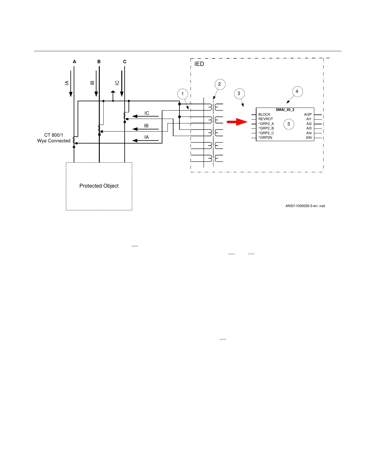
Figure 14: Wye connected three-phase CT set with its wye point away from the protected object
In the example, everything is done in a similar way as in the above described example
(Figure
13). The only difference is the setting of the parameter CTStarPoint of the used
current inputs on the TRM (item 2 in Figure 14 and 13):
• CTprim=600A
• CTsec
=5A
• CTWyePoint=FromObject
The ratio of the first two parameters is only used inside the IED. The third parameter as
set in this example will negate the measured currents in order to ensure that the
currents are measured towards the protected object within the IED.
A third alternative is to have the residual/neutral current from the three-phase CT set
connected to the IED as shown in Figure
14.
1MRK 511 401-UUS A Section 4
Analog inputs
Bay control REC670 2.2 ANSI 71
Application manual

 Loading...


