2
3
4
5
6
1
10
11
12
13
14
15
SGB4
SGB3
SGB2
SGB1
SGB5
X3.1
6 5 4 3 2 1
X4.1
1
2
3
4
5
6
7
8
9
11
12
16
17
SGR4
SGR3
SGR2 SGR1
SGR5
SO1
PO2
SO2
3 4 5 6 7 8 9 10 11 12 13 14 15 16 17 18 19
21 22 23 24
51P
50N
46
13
14
SGR7
SGR8
SO4
SO5
SGR6
SO3
X3.1
16 17 18 19 20 21 22 23 24
10
15
18
19
20
21
22
23
1
2
3
4
5
6
7
8
9
11
12
16
17
13
14
10
15
18
19
20
21
22
23
1
2
3
4
5
6
7
8
9
11
12
16
17
13
14
10
15
18
19
20
21
22
23
1
2
3
4
5
6
7
8
9
11
12
16
17
13
14
10
15
18
19
20
21
22
23
1
2
3
4
5
6
7
8
9
11
12
16
17
13
14
10
15
18
19
20
21
22
23
1
2
3
4
5
6
7
8
9
11
12
16
17
13
14
10
15
18
19
20
21
22
23
1
2
3
4
5
6
7
8
9
11
12
16
17
13
14
10
15
18
19
20
21
22
23
1
2
3
4
5
6
7
8
9
11
12
16
17
13
14
10
15
18
19
20
21
22
23
9
18
19
16
17
20
8
7
2
3
4
5
6
1
10
11
12
13
14
15
9
18
19
16
17
20
8
7
2
3
4
5
6
1
10
11
12
13
14
15
9
18
19
16
17
20
8
7
2
3
4
5
6
1
10
11
12
13
14
15
9
18
19
16
17
20
8
7
2
3
4
5
6
1
10
11
12
13
14
15
9
18
19
16
17
20
8
7
79
CBFAIL
PO3
PO1
1 2
~
X5.1
X5.2
I
I
I
I
SGF1...SGF5
SGL1...SGL8
DI3
DI2
DI1
DI4
DI5
Optional
Pickup
Trip
Blocking
Trip
Blocking
Arc light output
Trip
Indications cleared
Output contacts unlatched
Memorized values cleared
Setting group selection
Time sync
External Trip
External trip
Trip
Blocking
Blocking
Trip
Trip
Blocking
Trip
Alarm
Trip
External Arc
CB Position Open
CB Position Closed
CB Close Inhibit
External AR Initiation
Open CB Command
Close CB Command
CB Reclosing Failed
Shot Due
Definite Trip Alarm
AR Lockout
External Triggering
Reset
Trip lockout
Optional
External Triggering Trip
Warning
Light sensor 1
Light sensor 2
Trip lockout
Optional
Self-supervision
IRF
IRF
a
b
c
n
Pickup
Pickup
Pickup
Pickup
Pickup
AR Disable
Arc light output
Arc 51P/51N
49
Trip
50P-1
50P-2
51N
= Factory default
A060581
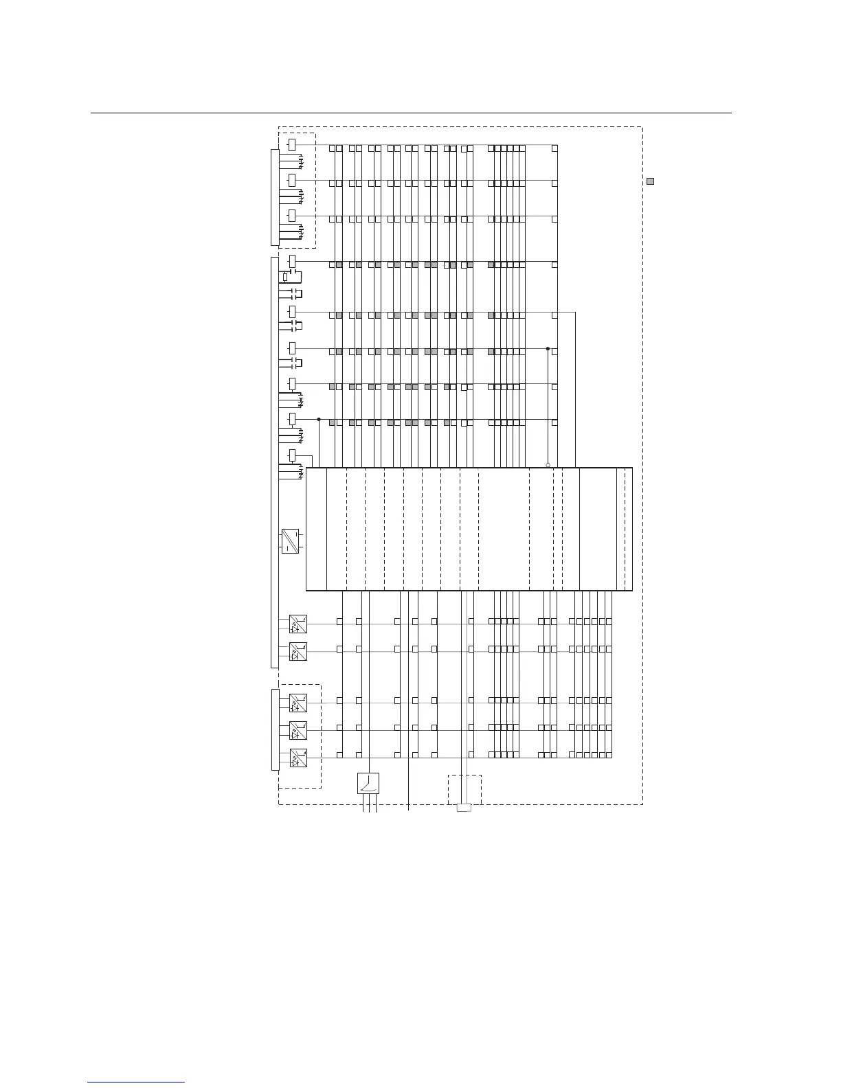
Fig. 5.1.3.-1 Signal diagram
The functions of the relay are selected with the switches of switchgroups SGF, SGB,
SGR and SGL. The checksums of the switchgroups are found under SETTINGS in
the HMI menu. The functions of the switches are explained in detail in the
corresponding SG_ tables.
26
REF610REF610
Feeder Protection Relay
Technical Reference Manual - ANSI Version
1MRS755535