-0.6 -0.4 -0.2 0 0.2 0.4 0.6 0.8
-0.4
-0.2
0
0.2
0.4
0.6
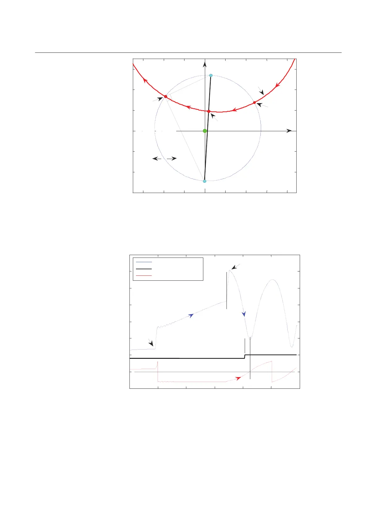
Real part (R) of Z in Ohms
→
Imaginary part (X) of Z in Ohms
→
R[Ohm]
no trip
region
loci of Z(R, X)
no trip
region
rotor angle
= ±180°
X[Ohm]
RE - Receiving End (infinite bus)
←
this circle
is loci of
the rotor
angle = 90°
2
relay
SE - Sending End (generator)
no trip
region
inside
circle
outside the
circle is the trip
region for
TripAngle <= 90°
3
here rotor
angle
is -90°
here
rotor angle
is +90°
1
trip
region
←
Z - line connects
points SE & RE
IEC10000114-1-en.vsd
IEC10000114 V1 EN
Figure 81: The imaginary offset Mho circle represents loci of the impedance
Z(R, X) for which the rotor angle is 90 degrees
0 200 400 600 800 1000 1200
-5
0
5
10
15
20
25
30
35
Current in kA, trip command to CB, rotor angle in rad
→
Time in milliseconds
→
pos. seq. current in kA
trip command to CB
rotor angle in radian
fault
occurs
←
normal load current
←
min. current
very high currents due
to out-of-step condition
←
after 1st
pole slip
←
2nd
←
rotor angle
angle towards 0°
current decreases
fault cleared
→
current increases under
fault conditions
→ ←
tBreaker = 60 ms
trip command
→
issued here
IEC10000115-1-en.vsd
IEC10000115 V1 EN
Figure 82: Trip initiation when the break-time of the circuit breaker is known
1MRK 502 048-UEN A Section 7
Impedance protection
171
Technical manual