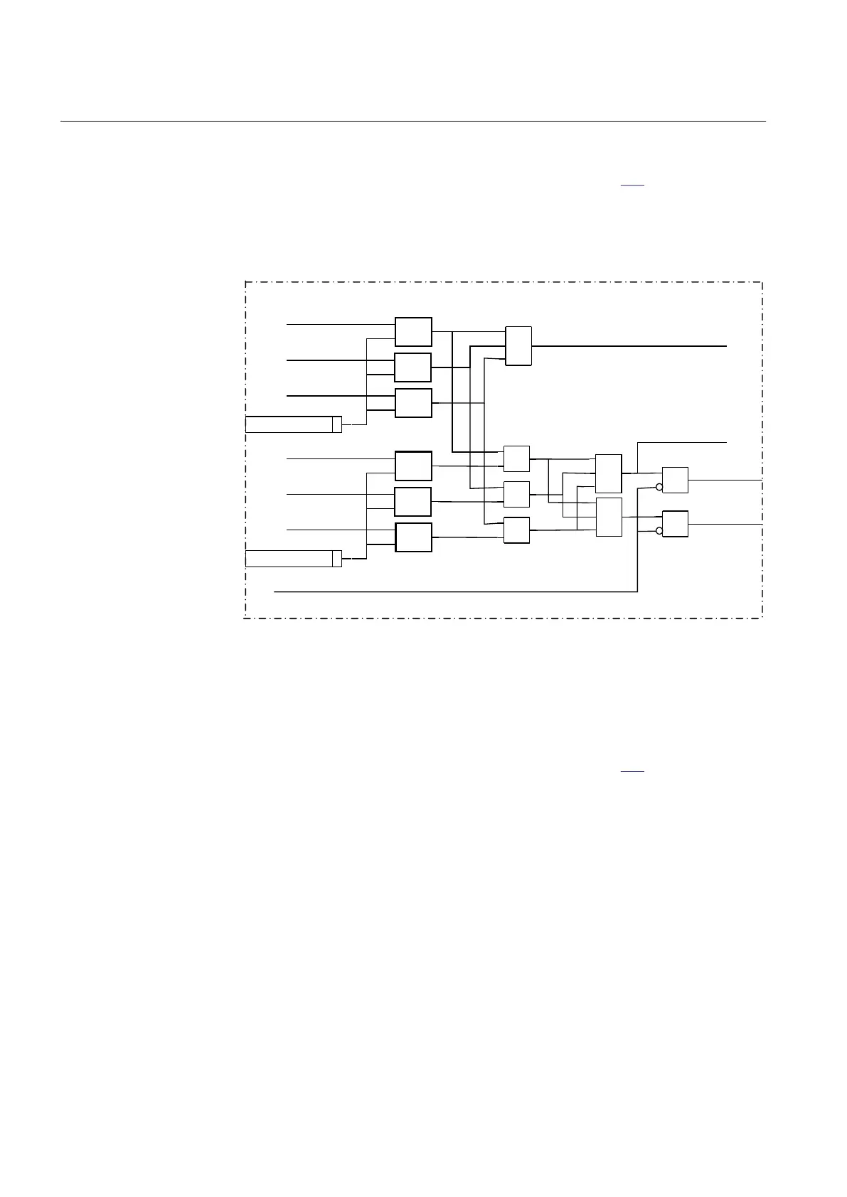
11.1.7.3 Dead line detection
A simplified diagram for the functionality is found in figure 159. A dead phase
condition is indicated if both the voltage and the current in one phase is below their
respective setting values UDLD< and IDLD<. If at least one phase is considered to be
dead the output DLD1PH and the internal signal DeadLineDet1Ph is activated. If all
three phases are considered to be dead the output DLD3PH is activated
IL1
IL2
IL3
a
b
a<b
a
b
a<b
a
b
a<b
IDLD<
UL1
UL2
UL3
a
b
a<b
a
b
a<b
a
b
a<b
UDLD<
OR
AND
AND
AND
AND
AND
AND
AND
AllCurrLow
DeadLineDet1Ph
DLD3PH
DLD1PH
intBlock
Dead Line Detection
IEC10000035-1-en.vsd
IEC10000035 V2 EN
Figure 159: Simplified logic diagram for Dead Line detection part
11.1.7.4 Main logic
A simplified diagram for the functionality is found in figure
160. The fuse failure
supervision function (SDDRFUF) can be switched on or off by the setting parameter
Operation to On or Off.
For increased flexibility and adaptation to system requirements an operation mode
selector, OpMode, has been introduced to make it possible to select different operating
modes for the negative and zero sequence based algorithms. The different operation
modes are:
• Off. The negative and zero sequence function is switched off.
• UNsINs. Negative sequence is selected.
• UZsIZs. Zero sequence is selected.
Section 11 1MRK 502 048-UEN A
Secondary system supervision
314
Technical manual