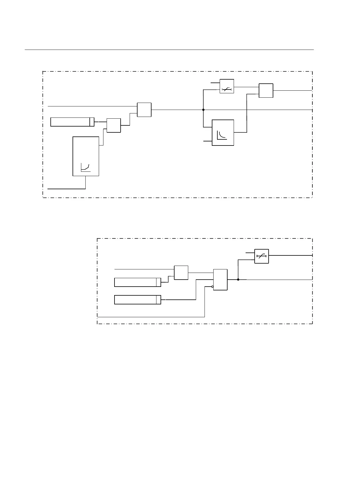
8.10.7.4 Logic diagram
IEC10000214-1-en.vsd
StartCurr
X
a
b
a>b
Voltage
control or
restraint
feature
Inverse
DEF time
selected
Inverse
time
selected
OR
STOC
TROC
MinPh-PhVoltage
MaxPhCurr
IEC10000214 V1 EN
Figure 128: Simplified internal logic diagram for overcurrent function
Operation_UV=On
StartVolt
AND
a
b
b>a
MinPh-phVoltage
BLKUV
IEC10000213-1-en.vsd
DEF time
selected
STUV
TRUV
IEC10000213 V1 EN
Figure 129: Simplified internal logic diagram for undervoltage function
8.10.7.5 Undervoltage protection
The undervoltage step simply compares the magnitude of the measured voltage
quantity with the set start level. The undervoltage step starts if the magnitude of the
measured voltage quantity is smaller than the set level.
Section 8 1MRK 502 048-UEN A
Current protection
254
Technical manual