Note that angle between U
3N
and U
3T
is typically close to 180°.
en06000448.vsd
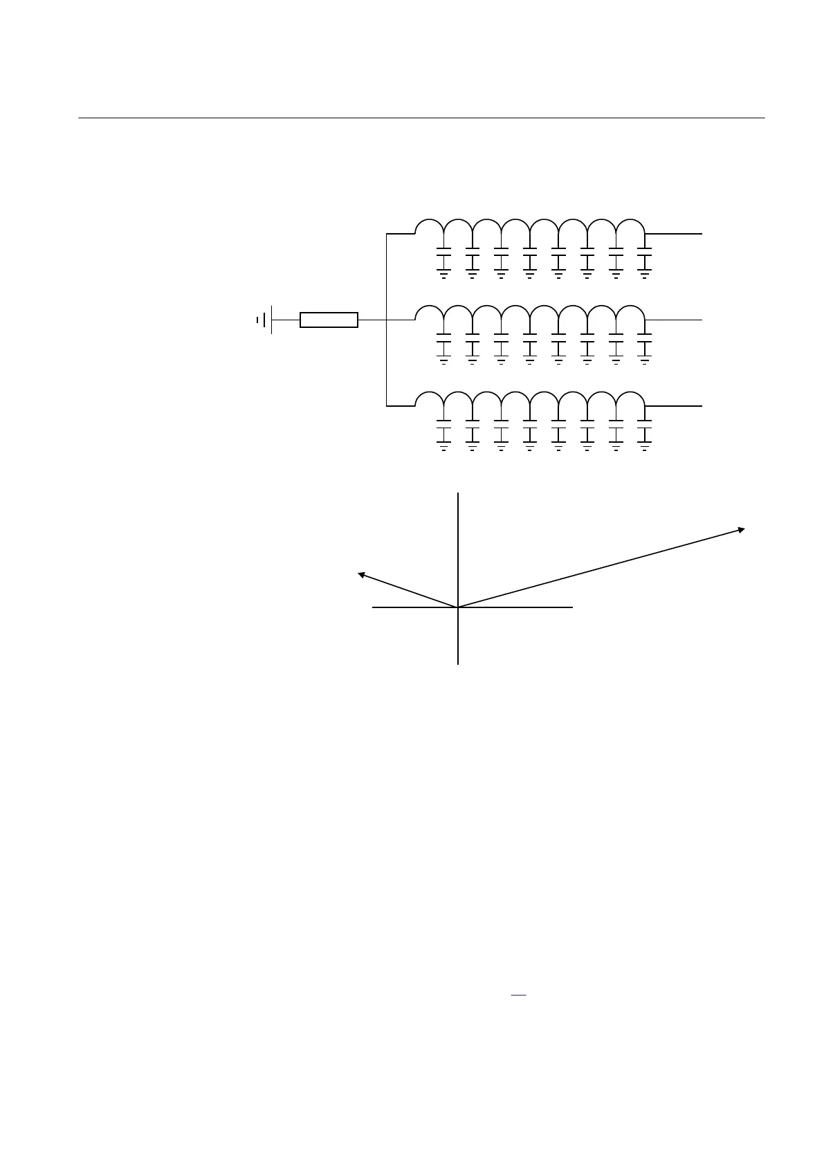
U
3N
U
3T
- DU
3
+
- U
3
+
- U
3N
+
+
U
3T,L1
-
+
U
3T,L2
-
+
U
3T,L3
-
IEC06000448 V2 EN
Figure 144:
Generator 3
rd
harmonic voltage characteristic at normal operation
The generator is modeled as parts of a winding where a 3
rd
harmonic voltage is
induced along the winding, represented by the end voltages U
3N
(voltage drop across
resistor) and U
3T
in the figure. Via the winding capacitances to earth and the neutral
point resistor there will be a small 3
rd
harmonic current, giving the voltages U
3N
and
U
3T
. The 3
rd
harmonic voltage in the generator neutral point (U
3N
) will be close to zero
in case of a stator earth-fault close to the neutral. This fact alone can be used as an
indication of stator earth-fault. To enable better sensitivity and stability also
measurement of the generator's 3
rd
harmonic voltage U
3T
is also used. In addition to
the decrease of U
3N
the generator voltage U
3T
will increase under the stator earth-fault
close to the generator neutral point. Therefore the 3
rd
harmonic voltage U
3T
, (which
is a zero sequence voltage) is used by the protection. In the 3
rd
harmonic voltage
differential protection algorithm equation
94 is used:
1MRK 502 048-UEN A Section 9
Voltage protection
289
Technical manual