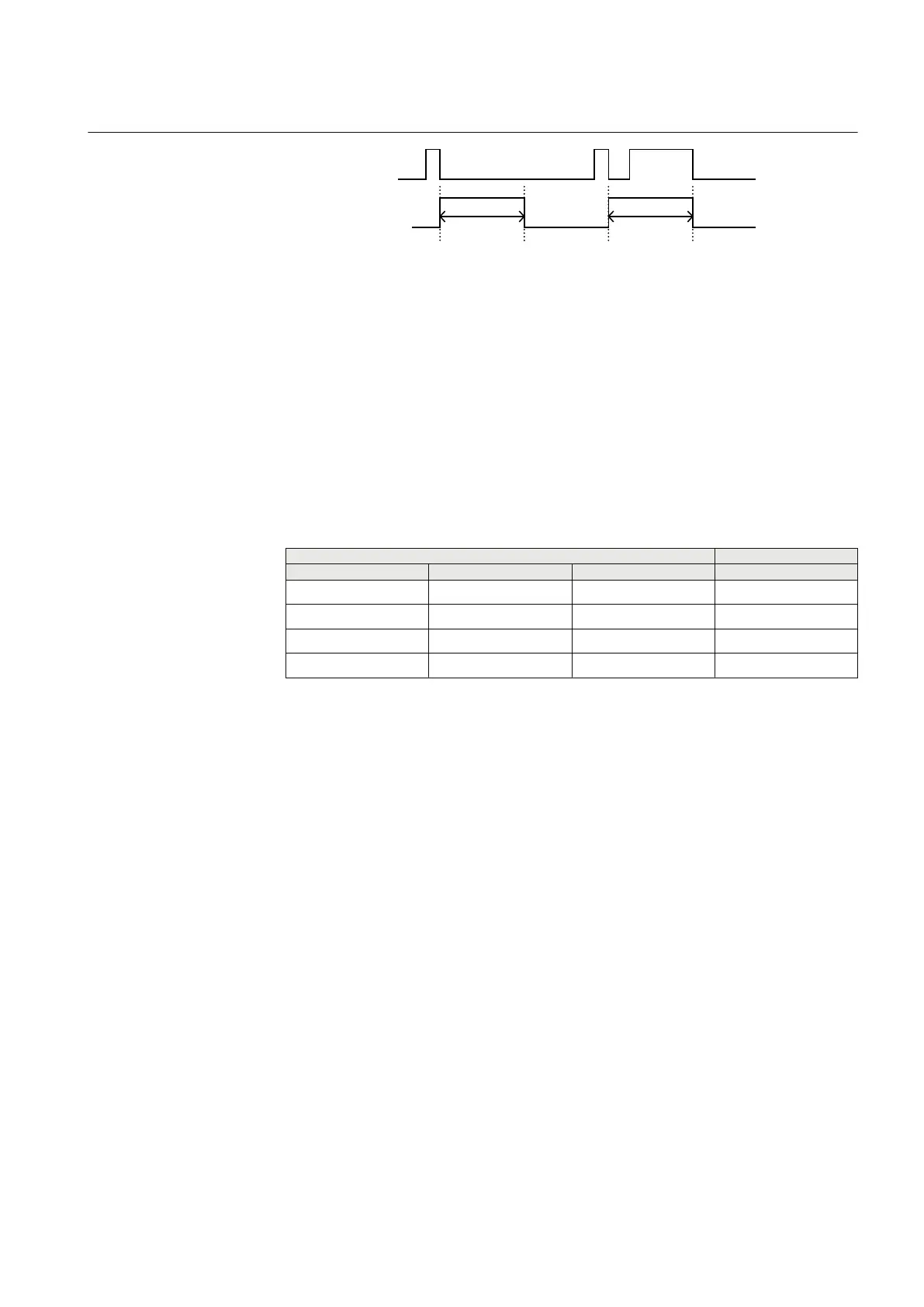
Input value
t
pulse
t
pulse
Output value
IEC09000332_1_en.vsd
IEC09000332 V1 EN
Figure 28: Sequence diagram for setting PULSED
Input function
All inputs work the same way: When the LHMI is configured so that a certain function
button is of type CONTROL, then the corresponding input on this function block
becomes active, and will light the yellow function button LED when high. This
functionality is active even if the function block operation setting is set to off.
There is an exception for the optional extension EXT1 function keys 7 and 8, since
they are tri-color (they can be red, yellow or green). Each of these LEDs are controlled
by three inputs, which are prioritized in the following order: Red - Yellow - Green
INPUT OUTPUT
RED YELLOW GREEN Function key LED color
1 0/1 0/1 red
- 1 0/1 yellow
- - 1 green
0 0 0 off
1MRK 502 048-UEN A Section 5
Local Human-Machine-Interface LHMI
79
Technical manual