12.6.2 Application
12.6.2.1 Fault current reversal logic
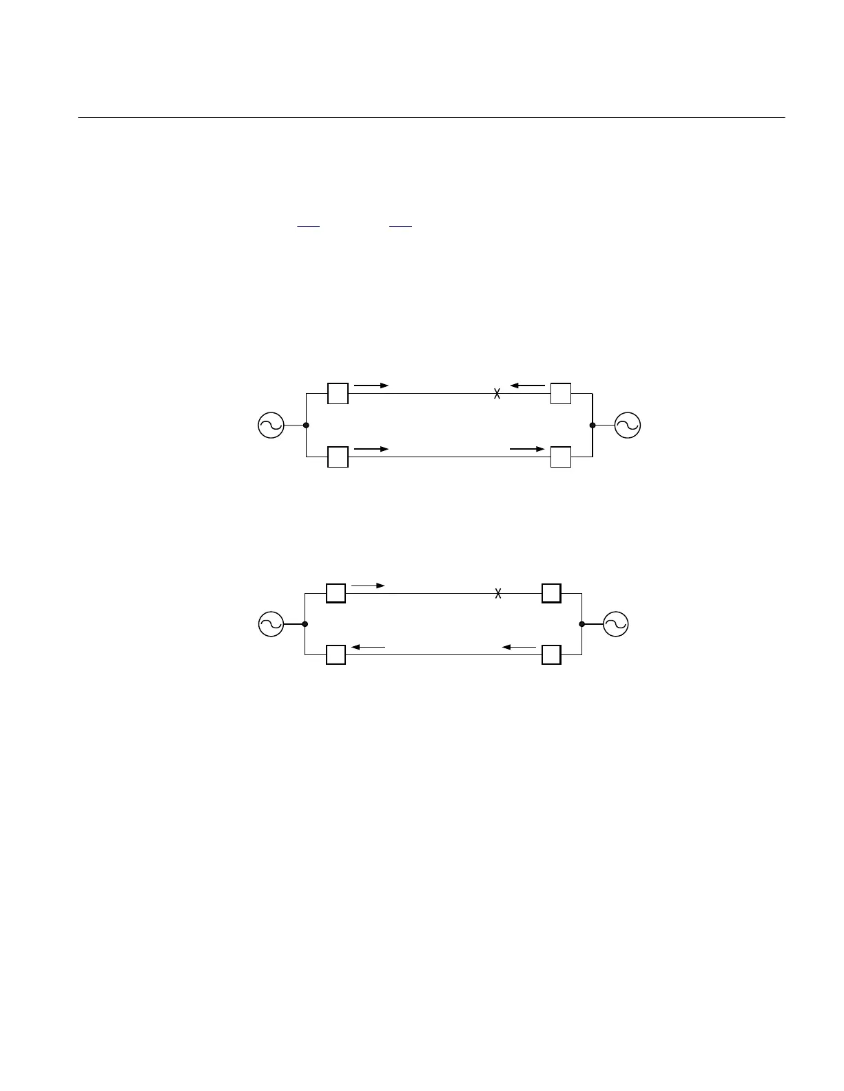
Figure 199 and figure 200 show a typical system condition, which can result in a fault
current reversal.
Assume that fault is near the B1 breaker. B1 Relay sees the fault in Zone1 and A1 relay
identifies the fault in Zone2.
It can cause an unselective trip on line L2 if the current reversal logic does not block the
permissive overreaching scheme in the IED at B2.
en99000043_ansi.vsd
Strong
source
LINE 1
LINE 2
A:1
A:2
B:1
B:2
A B
Weak
source
FAULT
CLOSED
CLOSED
CLOSED
CLOSED
ANSI99000043 V1 EN
Figure 199: Current distribution for a fault close to B side when all breakers are closed
en99000044_ansi.vsd
Strong
source
LINE 1
LINE 2
A:1
A:2
B:1
B:2
A B
Weak
source
CLOSED
CLOSED
OPEN
CLOSED
FAULT
ANSI99000044 V1 EN
Figure 200: Current distribution for a fault close to B side when breaker at B1 is
opened
When the breaker on the parallel line operates, the fault current on the healthy line is
reversed. The IED at B2 recognizes the fault in forward direction from reverse direction
before breaker operates. As IED at B2 already received permissive signal from A2 and
IED at B2 is now detecting the fault as forward fault, it will immediately trip breaker at B2.
To ensure that tripping at B2 should not occur, the permissive overreaching function at B2
needs to be blocked by IRVL till the received permissive signal from A2 is reset.
The IED at A2, where the forward direction element was initially activated, must reset
before the send signal is initiated from B2. The delayed reset of output signal IRVL also
1MRK 506 334-UUS A Section 12
Scheme communication
409
Application manual