Section 3 REL650 setting examples
3.1 Setting example for a two-ended overhead
transmission line in a solidly grounded network
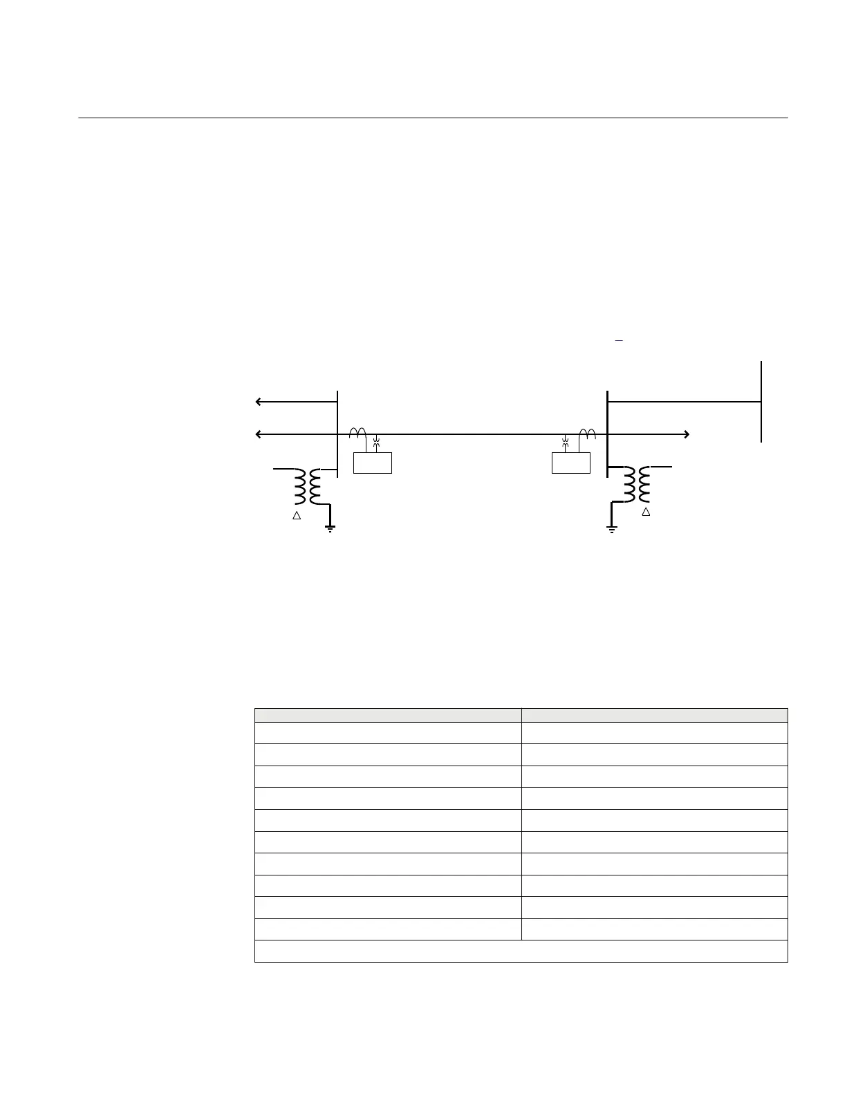
The application example: a 138 kV line as shown in figure 4
REL 650
REL 650
Z 1 = R 1 + jX 1
Z 0 = R 0 + jX0
A B
Y
Y
ANSI11000108_1_en.vsd
ANSI11000108 V1 EN
Figure 5: Two-ended overhead transmission line in a solidly grounded network
The following data is assumed:
Table 2: Data for the line application example
Entity
Value
Line length 50 km
Positive sequence impedance 0.05 + j 0.35 Ω/km ⇒ 2.5 + j17.5 Ω
Zero sequence impedance 0.15 + j 1.00 Ω/km ⇒ 7.5 + j50 Ω
High positive sequence source impedance at A j10 Ω (about 1 900 MVA)
Low positive sequence source impedance at A j3.2 Ω (about 6 000 MVA)
High zero sequence source impedance at A j8 Ω
Low zero sequence source impedance at A j5 Ω
High positive sequence source impedance at B j10 Ω (about 1 900 MVA)
Low positive sequence source impedance at B j3.2 Ω (about 6 000 MVA)
High zero sequence source impedance at B j8 Ω
Table continues on next page
1MRK 506 334-UUS A Section 3
REL650 setting examples
41
Application manual