3.1.11.3 Blocking scheme
The principle of the logic can be explained as shown in figure 29.
Z 1 = R 1 + jX 1
Z 0 = R 0 + jX0
A B
1
2
C
1
2
Communication
4 ( reverse)
4 ( reverse)
Y
Y
REL 650
REL 650
ANSI11000117_1_en.vsd
Step
Step
Step
Step
Step
Step
ANSI11000117 V1 EN
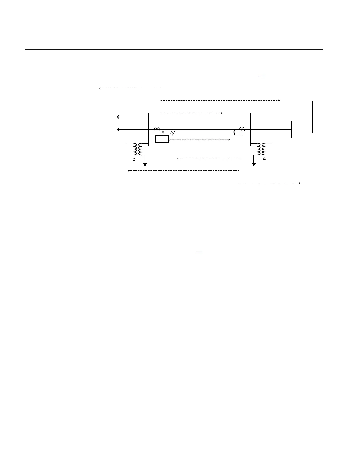
Figure 29: Principle for four step residual overcurrent protection blocking
communication scheme
A communication signal is sent (CS) if a fault is detected by step 4 (reverse direction).
When a communication signal is received (CR) the fast overreaching step 2 will be
blocked. The logic is shown in figure 30.
Section 3 1MRK 506 334-UUS A
REL650 setting examples
78
Application manual