Z 1 = R 1 + jX 1
Z 0 = R 0 + jX0
A B
Step 1- reach
C
Communication
Step 2- reach
Step 1- reach
Step 2- reach
Y
Y
REL 650
REL 650
ANSI11000115_2_en.vsd
ANSI11000115 V2 EN
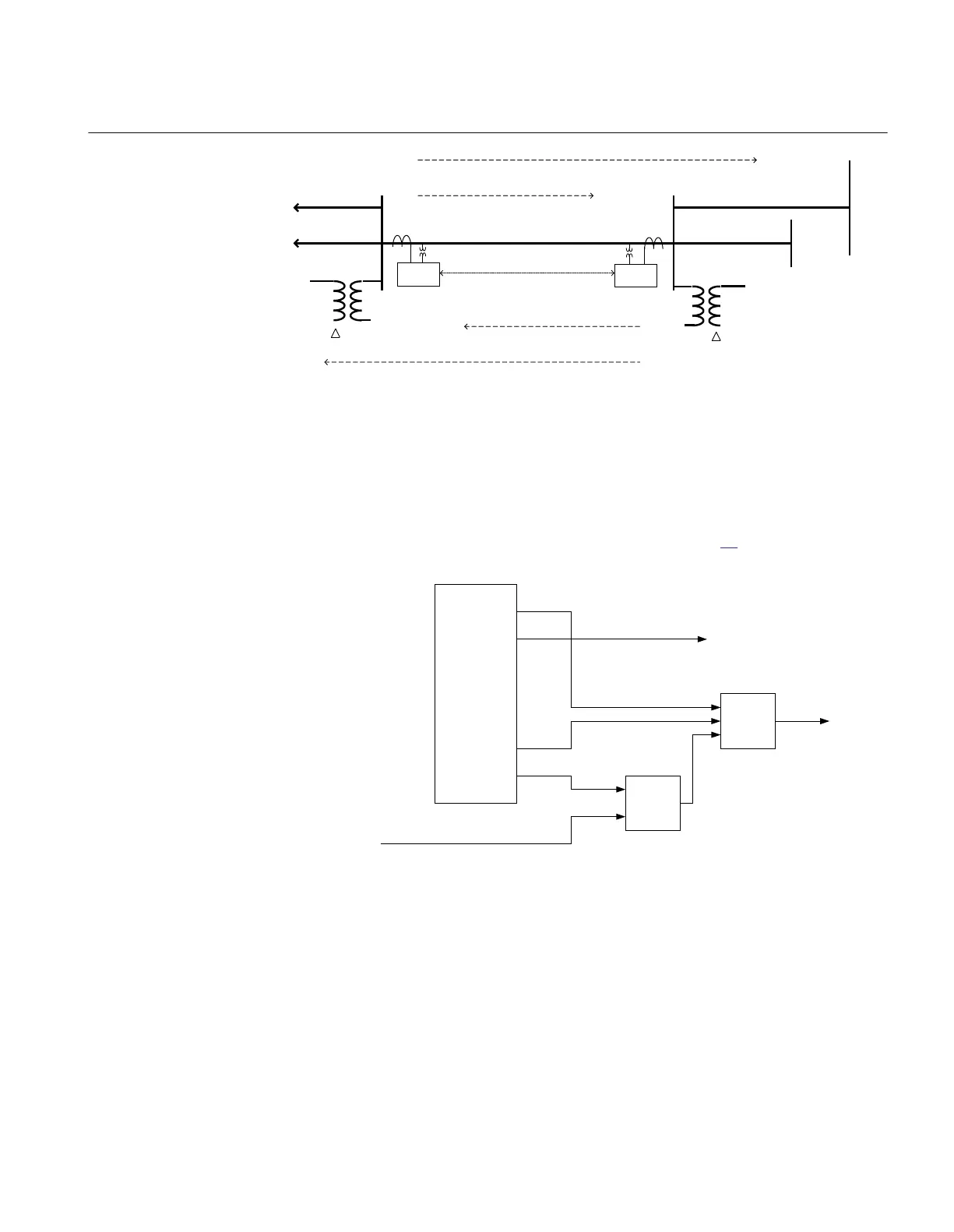
Figure 27: Principle for four step residual overcurrent protection underreach
communication scheme
A communication signal is sent (CS) if a fault is detected by step 1 (3I
0
>>> underreach
step). When a communication signal is received (CR) Step 2 (3I
0
>>) will operate
instantaneously. The logic can be described as shown in figure 28.
Send signal (CS)
Receive signal
(CR)
Trip
Step 1 TRIP
Step 1
PUST1
Step
2
TRIP
Step 2
ANSI11000079_1_en.vsd
EF4PTOC (51N_67N)
PUST2
OR
AND
ANSI11000079 V1 EN
Figure 28: Logic for four step residual overcurrent protection underreach
communication scheme
This scheme is used for long lines where it can be assured that the zone 1 reach from both
line ends will overlap each other.
1MRK 506 334-UUS A Section 3
REL650 setting examples
77
Application manual