A communication signal is sent (CS) if a fault is detected by step 2 (3I
0
>> overreach step).
When a communication signal is received (CR) Step 2 (3I
0
>>) operates instantaneously.
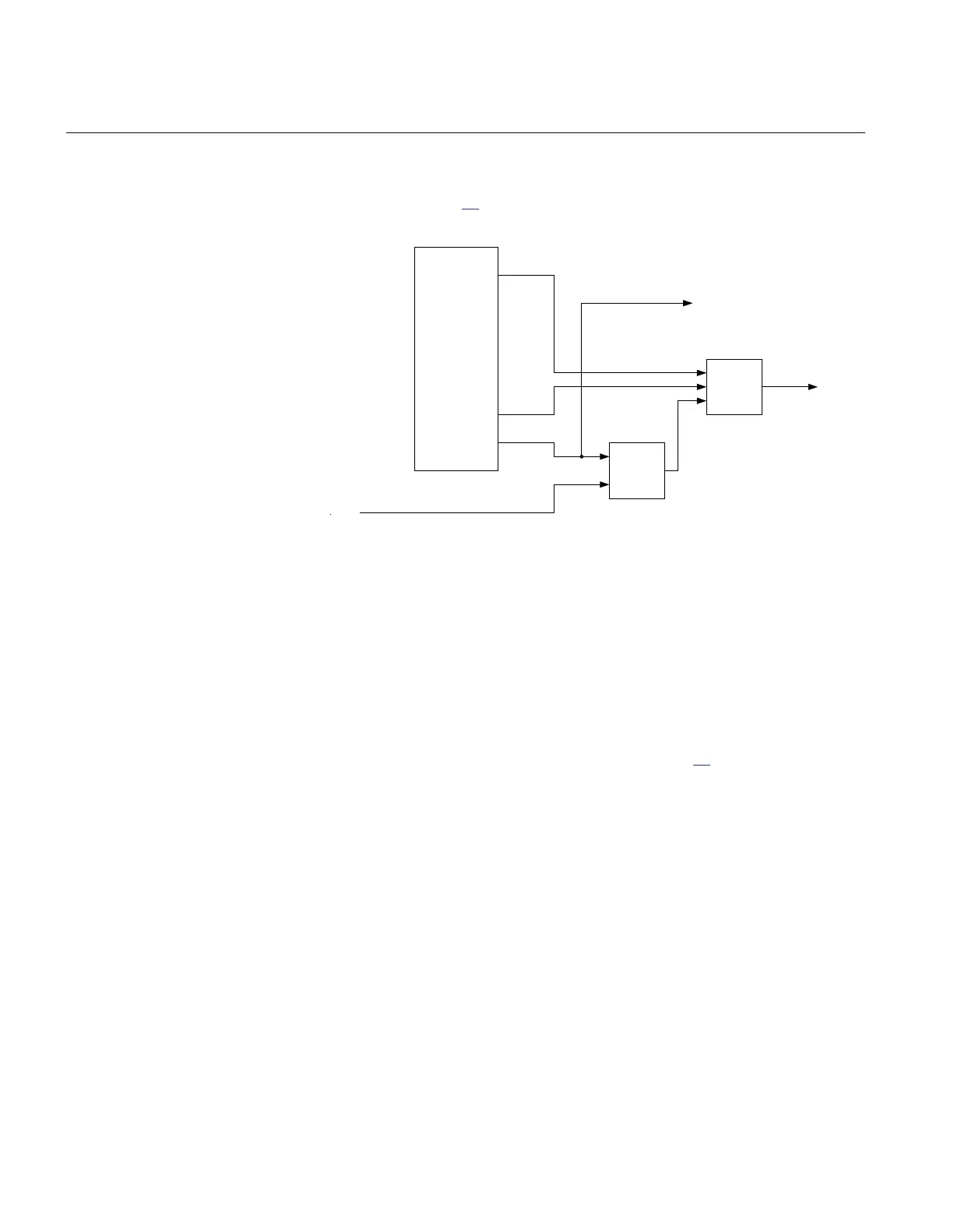
The logic is shown in figure 26.
Receive signal (CR)
Trip
EF4PTOC (51N_67N)
Step 1 TRIP
Step 1
PUST1
Step
2
TRIP
Step 2
Send signal (CS)
PUST2
OR
AND
ANSI11000078_1_en.vsd
ANSI11000078 V1 EN
Figure 26: Logic for four step residual overcurrent protection overreach
communication scheme
This scheme is used for short lines where it can not be assured that the zone 1 reach from
both line ends overlap each other. The scheme should also be used for lines where the fault
current infeed from one of the line ends is small and the weak end infeed logic is used.
3.1.11.2 Under-reach permissive logic
The principle of the logic can be explained as shown in figure 27.
Section 3 1MRK 506 334-UUS A
REL650 setting examples
76
Application manual