The residual overcurrent protection in line end A is considered. See figure 22. The same
principle can be used for the other line end.
3.1.10.1 Calculating general settings
1. Set GlobalBaseSel to 1
The settings are made in primary values. These values are given in the base settings
in Global base 1 (= 1000 A for this example).
2. Set DirModeSel1 and DirModeSel2 to Forward
The function shall be set directional forward for steps 1 and 2.
3. Set DirModeSel4 to Non-directional.
3.1.10.2 Calculating settings for step 1
1. Set Pickup1 to 300 % of IBase
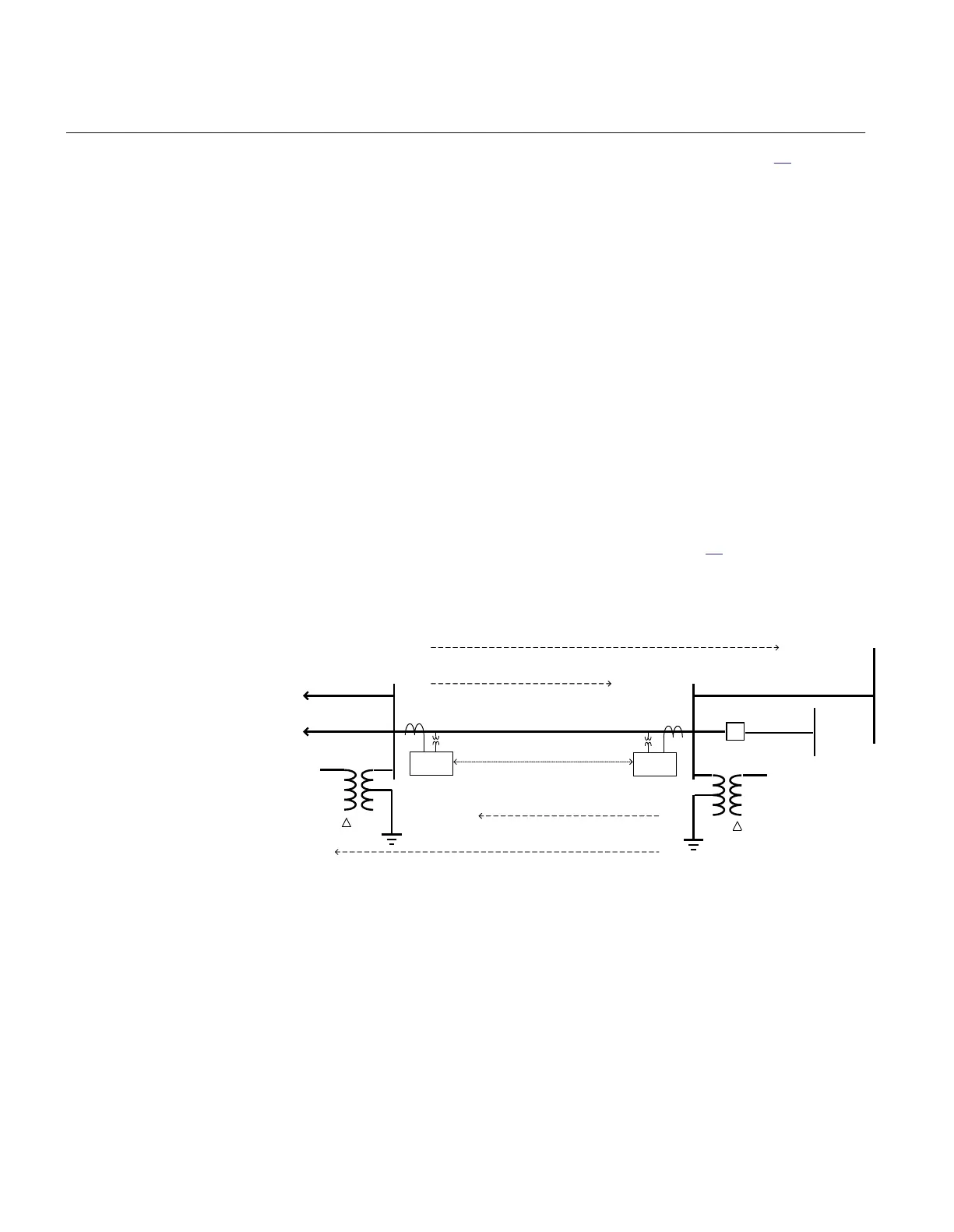
Busbar faults at the remote line end are applied, see figure
23. The following fault
types are applied: phase-phase-ground short circuit and phase-ground-fault. For the
faults shown in the figure, the source impedance (both positive sequence and zero
sequence) at line end A should be minimized (maximum short circuit power).
Z 1 = R 1 + jX 1
Z 0 = R 0 + jX0
A B
Step 1- reach
C
Communication
Step 2- reach
Step 1- reach
Step 2- reach
Y
Y
REL 650
REL 650
ANSI11000177_1_en.vsd
ANSI11000177 V1 EN
Figure 23: Fault case for step 1 calculation
The calculations provide the largest residual current to the protection 3I
0max
= 2.39
kA.
To assure selectivity the setting must fulfil:
I
high,set
= 1.2 · k · 3
I0max
Section 3 1MRK 506 334-UUS A
REL650 setting examples
72
Application manual