where k is the transient overreach (due to fault current DC-component) of the
overcurrent function. For the four step residual overcurrent function, k = 1.05.
2. Set t1 to 0 s
3.1.10.3 Calculating settings for step 2
1. Set Pickup2 to 140 % of IBase
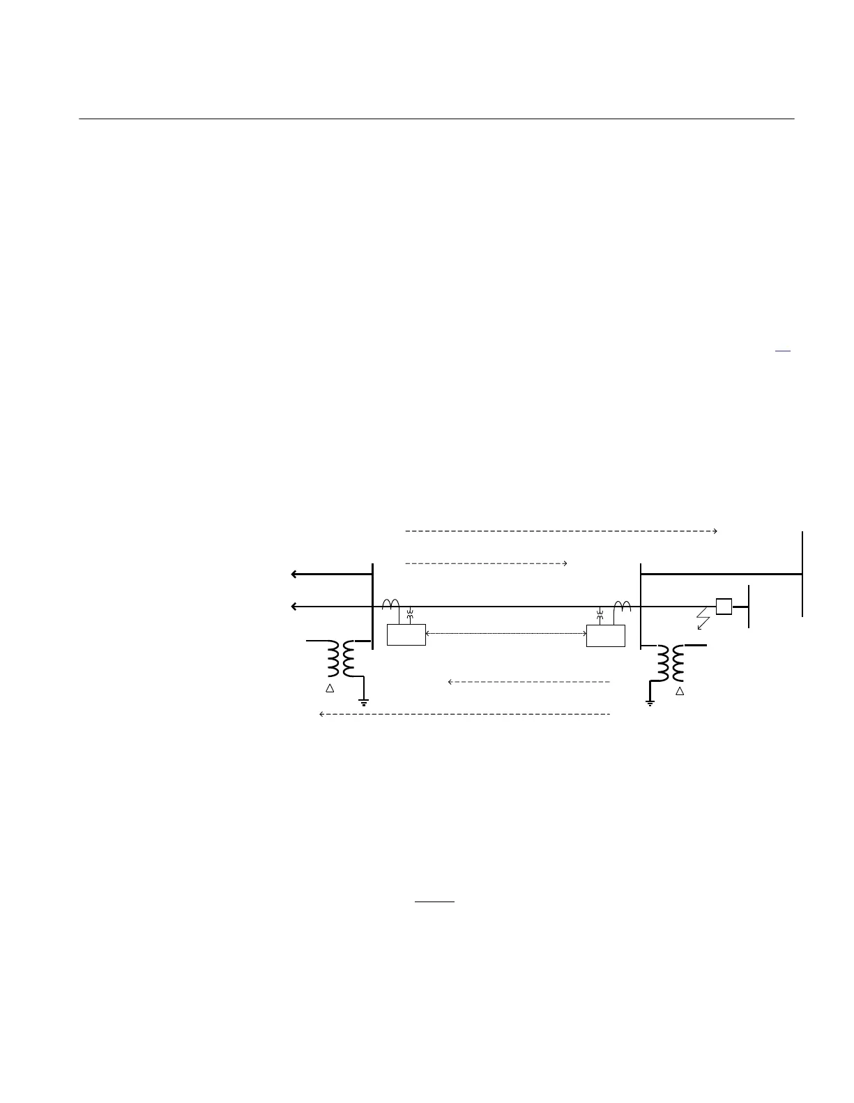
To assure that step 2 detects all short circuits on the line a phase-phase-ground and
phase-ground short circuit is applied at point 1 (the adjacent busbar), see figure 24.
The source impedance at line end A should be maximized (minimum short circuit
power) at this calculation. The residual current works out as
3I
0AB,min
= 2.39 kA
If possible the delay of 3I
0
>> should be set equal to the distance protection zone 2
(normally 0.4 s). To assure selectivity with this time delay the function should not
overreach adjacent lines out from the remote busbar and out from the local busbar.
To assure selectivity to ground-fault current protections of the other lines going out
from the remote busbar the following calculations shall be made.
Z 1 = R 1 + jX 1
Z 0 = R 0 + jX0
A B
Step 1- reach
C
Communication
Step 2- reach
Step 1- reach
Step 2- reach
Y
Y
REL 650
REL 650
ANSI11000116_1_en.vsd
ANSI11000116 V1 EN
Figure 24: Fault case for step 2 calculation
The calculated fault current fed to the protection is 3I
0,AB
. The calculated total fault
current fed to the fault point is 3I
0,BC
. The step 1 setting of the four step residual
overcurrent protection at line B – C is 3I
0BC,step1
. The current measured by the
ground-fault protection at an ground-fault at step 1 reach can be calculated:
BC
AB
stepBCsel
I
I
II
,0
,0
1,0,0
3
3
33 ×=
GUID-C1EC0C94-A9F7-4C8D-A0F2-1A63076EFC04 V1 EN (Equation 24)
1MRK 506 334-UUS A Section 3
REL650 setting examples
73
Application manual