Each individual tower foot has a resistance to ground up to 100 Ω, as the soil has very
high resistivity. The towers are however connected to each other via the shield wire
at the top of the towers, grounded to every tower. The effective tower footing
resistance is thus maximum 10 Ω.
R ≈ R
arc
+ R
towerfoot
= 1.1 + 10 Ω
This is the minimum value for the fault resistance reach RFPG1 setting. It can be
valuable to have much higher RFPG1 setting. it is proposed to set RFPG1 to 2 · Z1
(should never be larger than 4.5 · X1, where X1 is the reactive part of Z1):
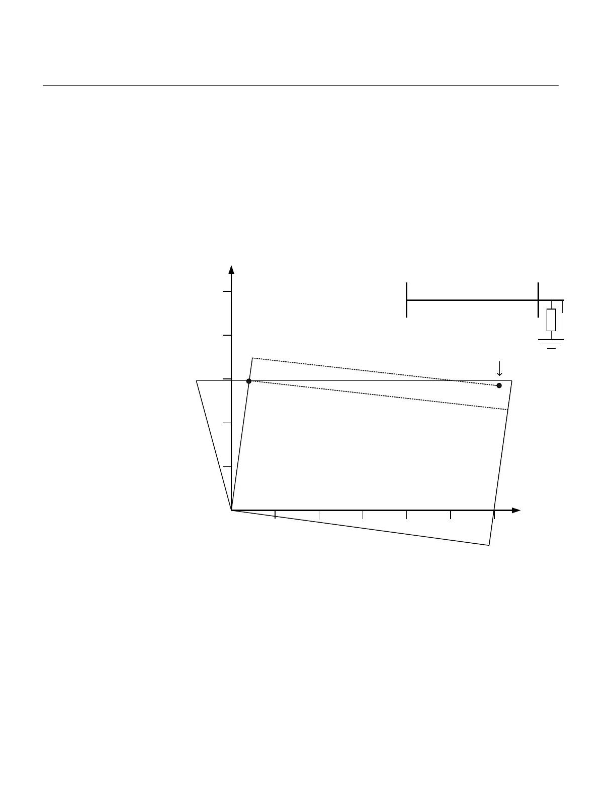
In case of load transfer at the line there is a risk of phase shift of the fault resistance
that moves the apparent impedance into the zone 1 characteristic even if the fault is
external.
R
X
5
10
15
20
5 10 15
Line impedance
20 25 30
Load current compensation
Resistive fault at load export
A
Rf
IEC09000411-1-en.vsd
IEC09000411 V1 EN
Figure 8: Load current compensation for zone 1 (quadrilateral characteristic)
The built in load current compensation of the zone 1 characteristic prevents
unwanted trip. This load compensation feature is present in zone 1 phase to ground
measuring element for quadrilateral characteristic.
7. Set OpModetPGZ1 to Enabled.
Zone 1 phase to ground loop gives trip.
8. Set OpModetPPZ1 to Enabled.
Section 3 1MRK 506 334-UUS A
REL650 setting examples
50
Application manual
 Loading...


