Step no. Changes after step 2 Expected output
TRIP Signal Test
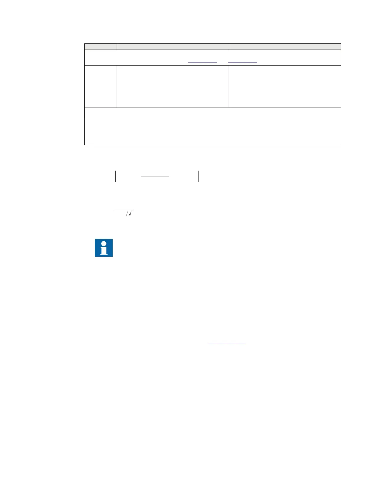
Repeat Sub-step 4–a and Sub-step 4–b
4-h Inject U
TapL1
= 31.00 V in secondary at rated
frequency
• BFI_3P and PU_A signals should
become HIGH after a time delay given by
the setting tDefTrip
• TRIP and TR_A signals should become
HIGH, if BlockTrip is set to Trip enabled
• PUDIFL1 should show 11.22%
- Steps 4–f, 4–g and 4–h can also be done phase wise.
* - UBase is considered as 400 kV and VT ratio as 400 kV/110 V
The voltage inputs U
L1
, U
L2
, and U
L3
refer to the bus voltages and U
TapL1
refers to the tap voltage of phase L1.
** - This step should be done only during Factory Acceptance Test (FAT). At field, the testing should be done with
the stored field values.
To calculate PUDIFL1 in steps 4-f, 4-g and 4-h, use the following equations:
11
1
1
1
LN TapLN
UDIFL U U U U
USEDURATL
IECEQUATION19128 V1 EN-US (Equation 115)
IECEQUATION19129 V1 EN-US (Equation 116)
The SCPDPTOV function will be blocked if any one of the phase bus voltage or all
three tap voltages equivalent to bus voltage (UTAPLx/USEDURATLx) goes below
the UMin> setting.
11.7.3.2 Completing the test
GUID-FEA7B2D1-3F4A-43FD-98F8-EC3584E5B511 v1
Continue to test another function or end the test by navigating to Main menu/Test/IED test mode/
TESTMODE: 1 and change the IEDTestMode setting to Off. Restore connections and settings to their
original values, if they were changed for testing purposes.
11.7.4 Voltage unbalance protection of shunt capacitor bank, SCUVPTOV
GUID-C41B59C8-9CA0-4B5F-9F90-354804BC1449 v1
GUID-CEB4E17E-DBDC-4201-BDC2-043E6F73BCD6 v1
Prepare the IED for verification of settings outlined in
Section 10.1.2.
11.7.4.1 Verifying the signals and settings
GUID-562427DE-2ADB-47DC-9E67-96626887C32F v1
GUID-3A4104C3-B362-44E2-B84E-1790D47B07FE v1
Ensure that mandatory three-phase and neutral voltages are connected to the separate SMAI blocks and
their outputs are connected to the U3P and U3NEUT inputs of the SCUVPTOV function.
1. Set the following parameters:
• Operation = ON
• tDefTrip = 5.00 s; tDefAlm = 5.00 s; tDefWrn = 5.00 s
• UNUnbal> = 5.5% UBase
Section 11 1MRK 504 165-UUS Rev. J
Testing functionality by secondary injection
226 Transformer protection RET670
Commissioning manual
© 2017 - 2021 Hitachi Power Grids. All rights reserved

 Loading...


