Operation Manual / 4 Product description / A100-L
8 Disassembly and assembly / 8.13 Fitting diffuser, wall insert
© Copyright 2017 ABB. All rights reserved. HZTL4034_EN Revision K June 2017
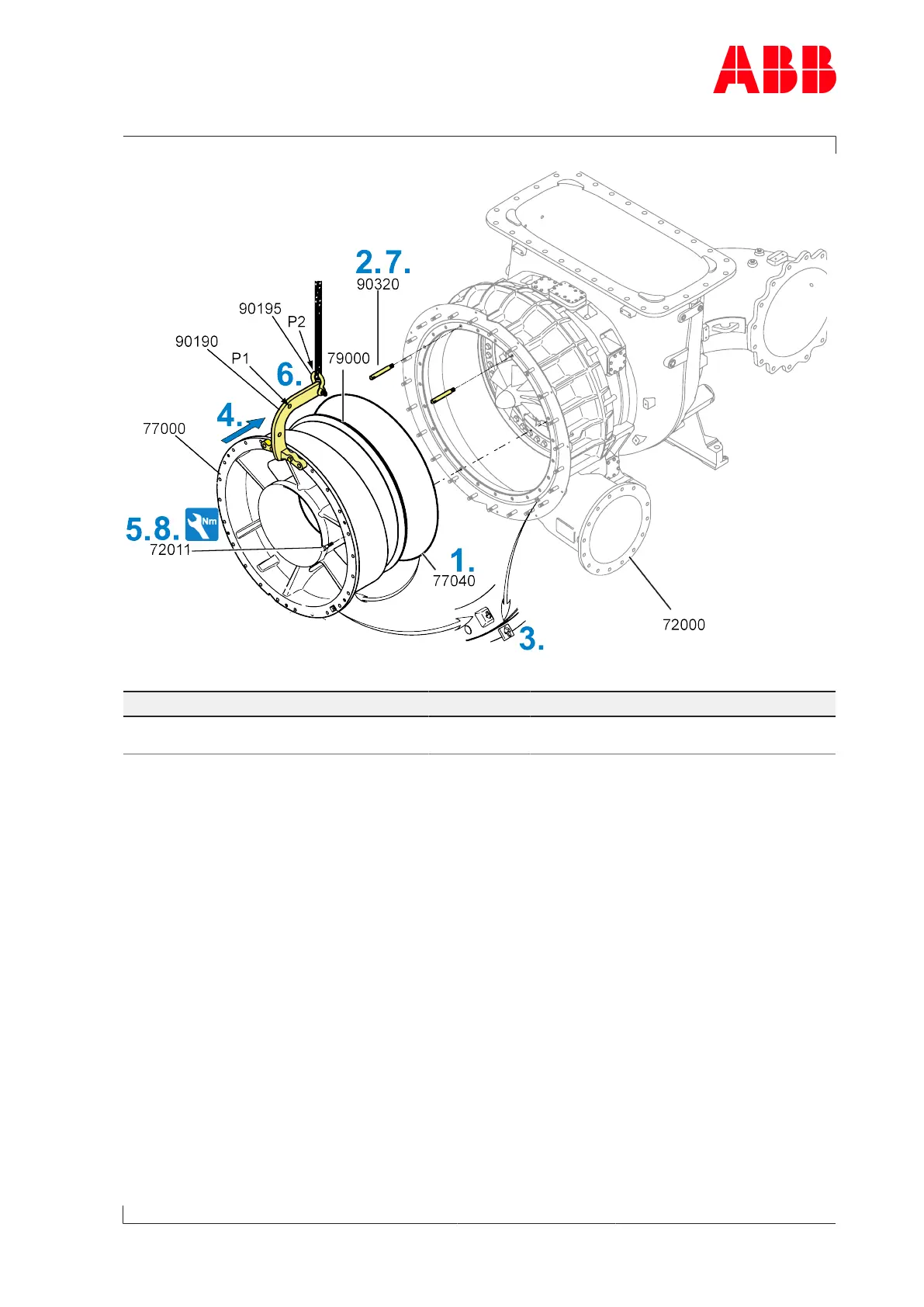
Fig.54: Fitting the wall insert
Part number A165-L A170-L A175-L A180-L A185-L A190-L
72011 M18
370Nm
M20
500Nm
M24
900Nm
M27
1300Nm
M30
1700Nm
M33
2300Nm
Table37: Tightening torque (72011)
1. Attach the new O-ring(77040) to the wall insert(77000).
2. Fit two guide studs (90320) in the upper area of the compressor casing (72000).
3. Align arrow markings of wall insert(77000) and compressor casing to one another.
4. Carefully move the wall insert with diffuser(79000) over the guide studs into the com-
pressor casing.
5. Fit a screw(72011) as a safeguard.
6. Change the position of the shackle (90195) with the lifting gear to P1 of the lifting device
(90190) and remove with the crane.
7. Completely insert the wall insert and then remove the guide studs (90320).
Check that both casings are in the correct position (the marking arrows are aligned to
one another).
8. Fit screws (72011).
Page 81 / 106