EN - 24
6 Putting into operation TCS-Compact
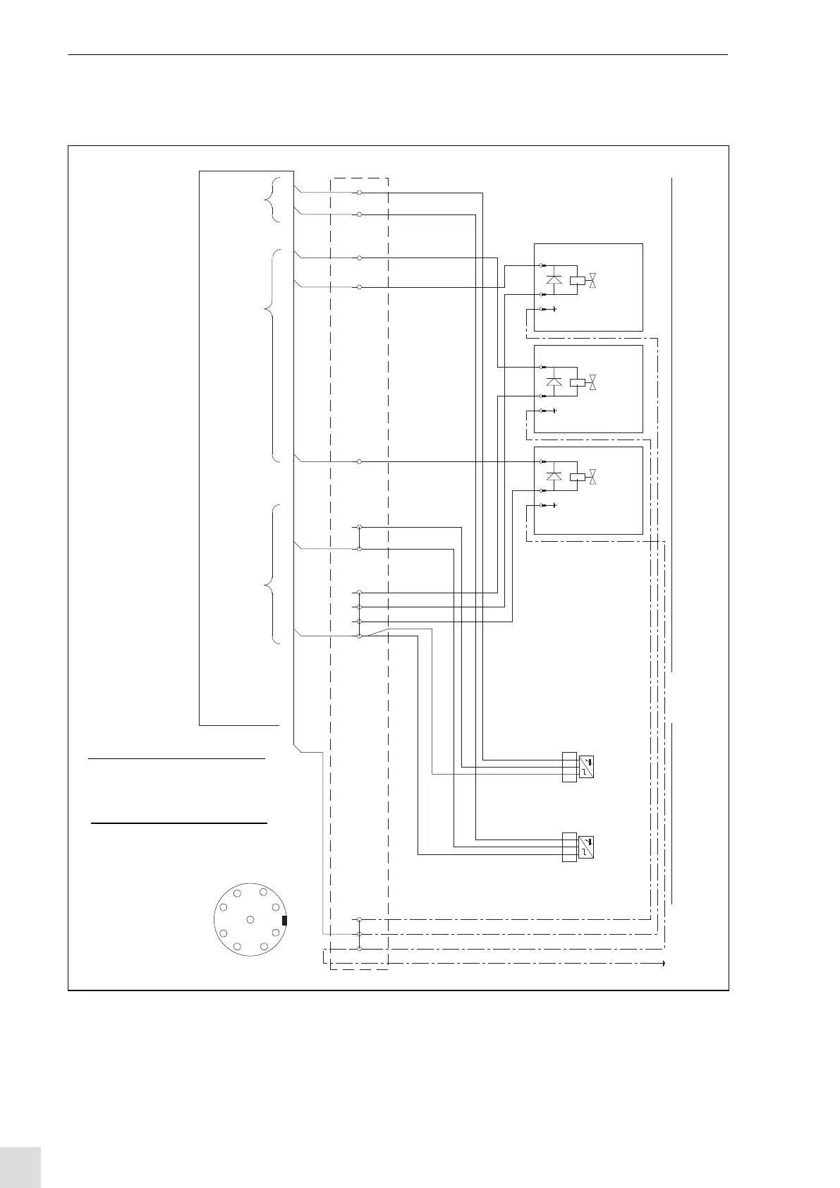
6.4 Establishing the electrical connection
Fig. 20 Circuit diagram
Current supply
GND
24VDC
Solenoid coils
Proximity switch
Switch outputs
-X1.13
-X1.14
-X1.12
-X1.11
-X1.10
BN
BN
BN
Clamp open (S2)
Lift down (S1)
Motor rotation (Y3)
Lift up (Y1)
Clamp open /
-X1.9
-X1.8
BN
BN
-X1.7
-X1.6
-X1.5
-X1.4
BU
BU
BU
GNDTerminal strip X1
-X1.3 PE
-X1.2 PE
-X1.1 PE
-S2
Clamp
open
Lift down signal
-S1
PE1
Sensors
Actuators
Clamp open /
wire cutter closed
Lift up
Motor rotation
PE
BU
BN
-D
A2
-Y3
A1
-Y2
-Y1
-D
A1
A2
BN
BU
PE
BN
BU
-D
PE
A2
A1
connector
1
2
3
4
5
6
7
8
BK
BK
(Y2)
wire cutter closed
8 Clamp open
7 Lift down 24VDC/max.100mA
6 Motor rotation (Y2) 24VDC/2,8W
5 Lift up (Y1) 24VDC/2,8W
4 Clamp closed /
3 24 VDC/200 mA
2 GND
1 PE
9 n.c.
wire cutter on (Y3) 24VDC/2,8W
24VDC/max.100mA
Output
Input
Operating
voltage
1
2
3
4
5
6
7
8
9
Caution 2 Versions are possible:
1) PNP-Output: Source type
2) NPN-Output: Sink type
Sensor version: see nameplate
Check polarity of clamping
valve plug,
diodes in solenoid
chance if neessary