7. Interrupt controller A96G174/A96S174 User’s manual
0 (Bit0)
Interrupt
Group
1 (Bit1)
2 (Bit2)
3 (Bit3)
4 (Bit4)
5 (Bit5)
Interrupt 0 Interrupt 6 Interrupt 12 Interrupt 18
Interrupt 1 Interrupt 7 Interrupt 13 Interrupt 19
Interrupt 2 Interrupt 8 Interrupt 14 Interrupt 20
Interrupt 3 Interrupt 9 Interrupt 15 Interrupt 21
Interrupt 4 Interrupt 10 Interrupt 16 Interrupt 22
Interrupt 5 Interrupt 11 Interrupt 17 Interrupt 23
Highest
Lowest
Highest Lowest
Figure 15. Interrupt Group Priority Level
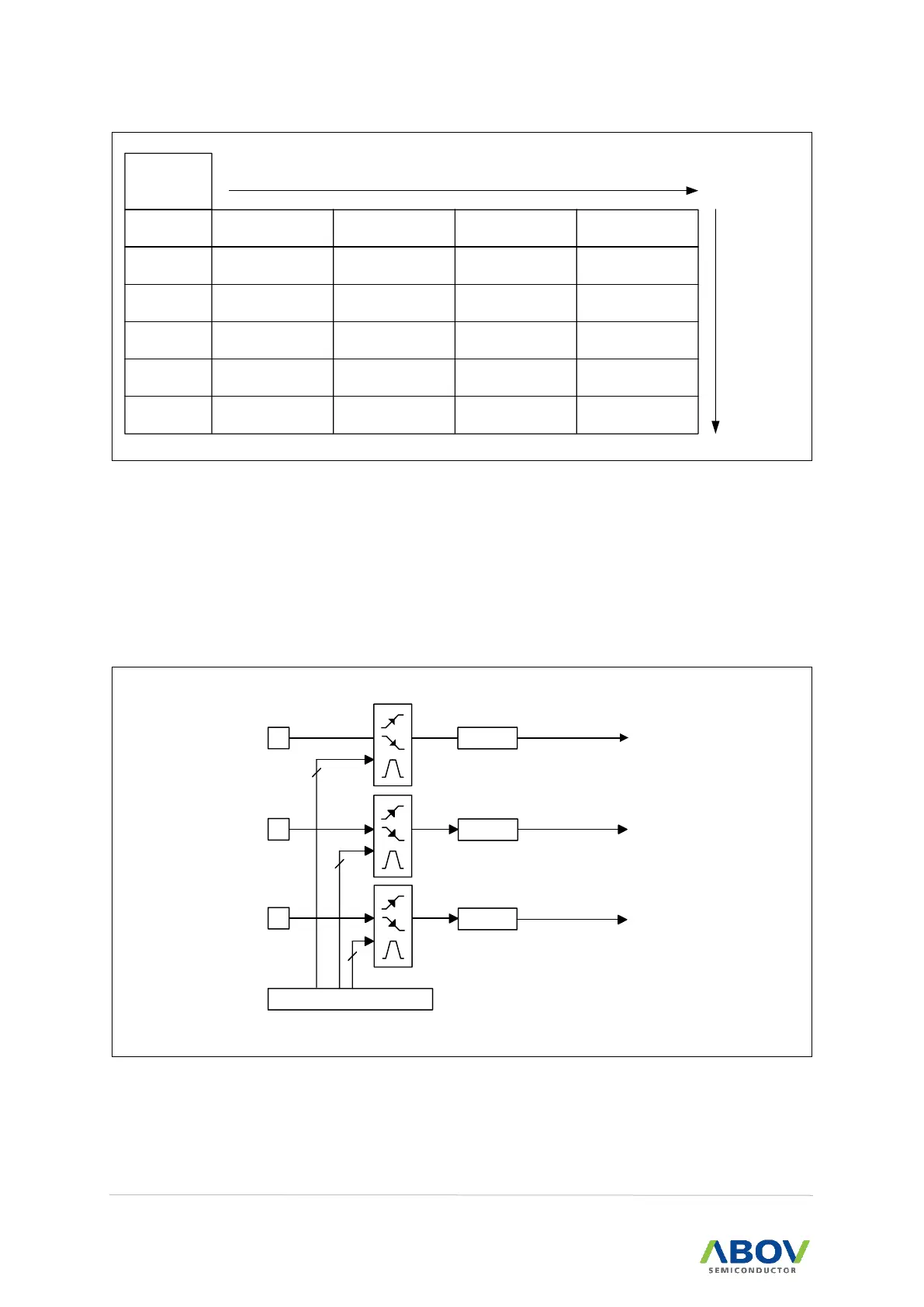
7.1 External interrupt
The external interrupt on EINT0, EINT1 and EINT2 pins receive various interrupt request depending on
the external interrupt polarity register (EIPOL) as shown in Figure 16. Also each external interrupt
source has enable/disable bits. The External interrupt flag register (EIFLAG) provides the status of
external interrupts.
EINT1 Pin
FLAG1
EINT0 Pin
FLAG0
EIPOL
2
2
INT1 Interrupt
INT0 Interrupt
EINT2 Pin
FLAG2
2
INT2 Interrupt
Figure 16. External Interrupt Description

 Loading...


