EasyManua.ls Logo

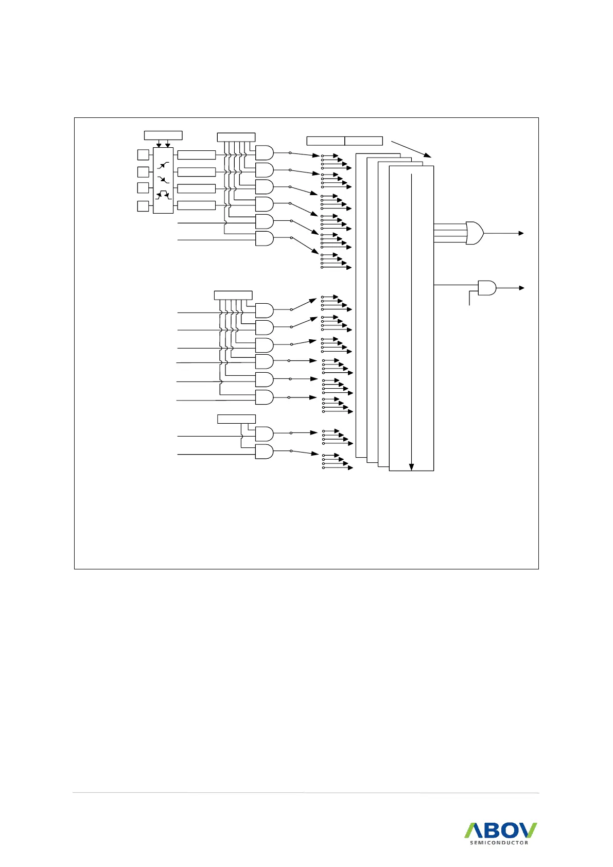
Abov A96G174 - Block Diagram; Figure 18. Interrupt Controller Block Diagram

Abov A96G174
211 pages
Print Icon
To Next Page IconTo Next Page
To Previous Page IconTo Previous Page
Loading...
7. Interrupt controller A96G174/A96S174 User’s manual
58
7.3 Block diagram
0
0
0
0
Priority High
1
1
1
1
2
2
2
2
3
3
3
3
4
4
4
4
5
5
5
5
6
6
6
6
7
7
7
7
8
8
8
8
9
9
9
9
10
10
10
10
11
11
11
11
Priority Low
EA
Release
Stop/Sleep
EINT0
EIFLAG.1
EIFLAG.2
EINT1
IP1IP
IE
FLAG0
FLAG1
EIPOL
Level 0
Level 1
Level 2
Level 3
IE1
USART RX
I2C
T0 Match
T1 Match
T2 Match
LVI
IE2
ADC
WDT
BIT
FLAG2
EINT2
USART TX
12
12
12
12
13
13
13
13
FLAG3
PCI
NOTES:
1. The release signal for stop/idle mode may be generated by all interrupt sources which are enabled
without reference to the priority level.
2. An interrupt request is delayed while data are written to IE, IE1, IE2, IE3, IP, IP1, and PCON
register.
Figure 18. Interrupt Controller Block Diagram

Table of Contents