After a reset, IP and IP1 are cleared to ‘00H’. If interrupts have the same priority level, lower number
interrupt is served first.
7.12.3 External Interrupt Flag Register (EIFLAG0 and EIFLAG1)
External Interrupt Flag 0 Register (EIFLAG0) and External Interrupt Flag 1 Register (EIFLAG1) are set
to ‘1’ when the external interrupt generating condition is satisfied. These flags are cleared when the
interrupt service routine is executed. Alternatively, these flags can be cleared by writing ‘0’ on to
themselves.
7.12.4 External Interrupt Polarity Register (EIPOL0L, EIPOL0H, and EIPOL1)
External Interrupt Polarity0 high/low Register (EIPOL0H/L) and External Interrupt Polarity1 Register
(EIPOL1) determines an edge type from rising edge, falling edge, and both edges of interrupt. Initially,
default value is no interrupt at any edge.
7.12.5 Register map
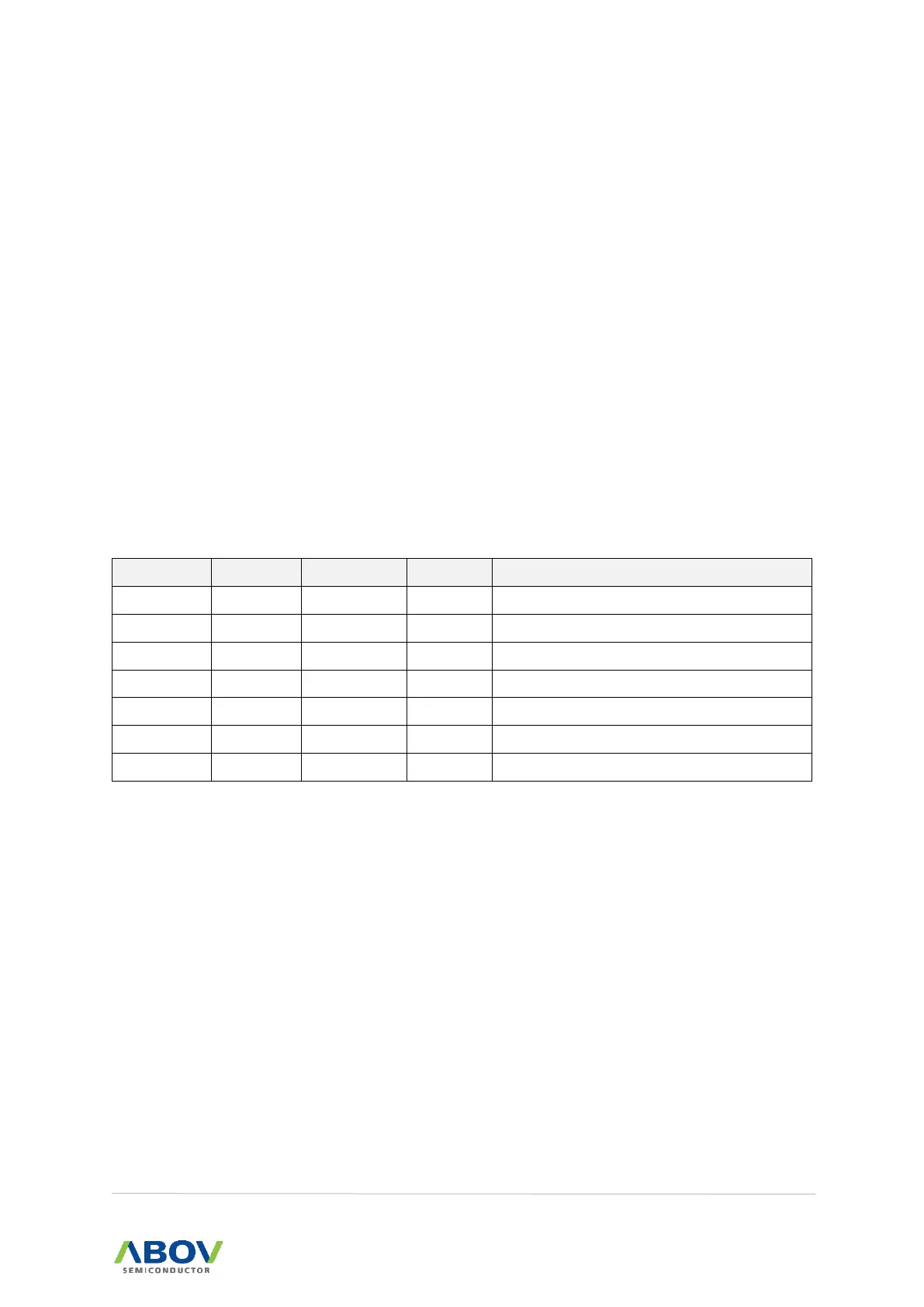
Table 9. Interrupt Register Map


 To Next Page