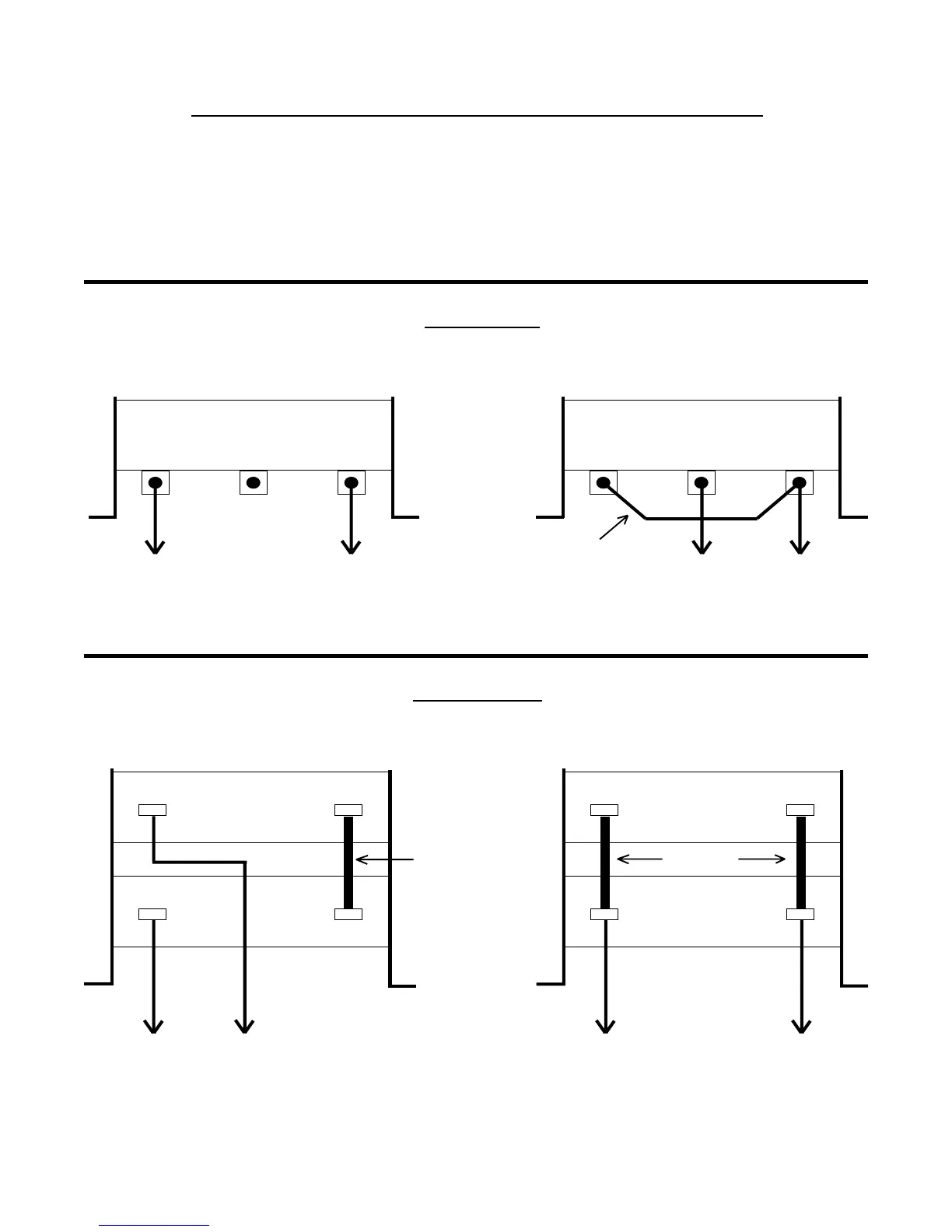
DIAGRAM B RESISTOR CONFIGURATIONS
If the Dynamic Braking Kit is ordered separately from the MC Series drive, the resistor assembly will be shipped in the 480
Vac and 590 Vac configuration. Therefore, for 240 Vac units, the resistor configuration must be modified, as shown below,
using the hardware included with the kit.
NOTE:
If the Dynamic Braking option is ordered with the drive, the resistor assembly will be shipped in the proper
configuration, and no modification is required.
Add jumper wire between Tab #1 and Tab #3, and move the RED wire to Tab #2.
Connect each Tab #1 together with screw provided (copy the configuration of the #2 tabs), and move the
BLUE wire to Tab #2.
123 123
JUMPER
WIRE
RED BLUE RED BLUE
12
12
12
12
RED BLUE BLUERED
7.5 - 25 HP
480 Vac & 590 Vac 240 Vac
0.5 - 5 HP
480 Vac & 590 Vac 240 Vac
SCREW
SCREW