22
RTCA SP Instrument Operator’s Manual
B
B
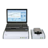
Keypad and indicators:
Power LED, solid green if power is on.
Communication LED, blinks if communication between RTCA SP Station and RTCA
Analyzer is active.
Status LED, indicates system status. Solid green if power is on, blinks green if measurement
is in progress, also blinks green once if self-test is passed. Red indicates a system error,
such as failed self-test, no station or communication error.
Self-test button, the status LED will ash green once if test is passed. It is RED if self-
test is failed.
Front
Panel
Power Status Self-testCommuniction
Figure 6: The RTCA Analyzer front panel.
RTCA Analyzer Cat. No. 05228972001
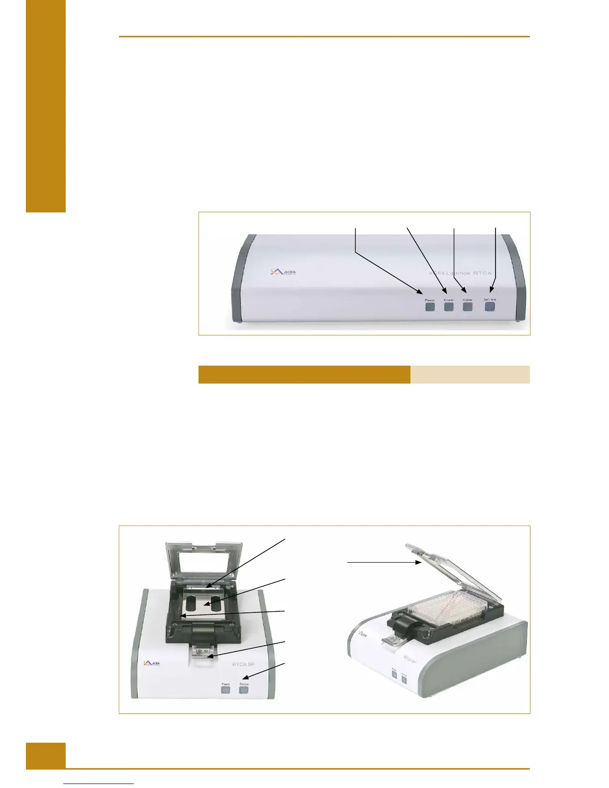
2.2 Description of the RTCA SP Station
e RTCA SP Station is placed inside the incubator and used to connect E-Plates 96 to the
RTCA Analyzer. Appropriate connection and precision electronic switches in the RTCA
SP Station enable so ware control or selection of individual electrode sensors within an
E-Plate 96 to be measured by the RTCA Analyzer.
e cradle pocket of the RTCA SP Station contains 120 individual, spring-loaded RTCA
Contact Pins 96, each for connecting to one of the 120 conductive pads on the back of an
E-Plate 96.
Cradle Pocket
Clamp Plate
RTCA Protector
Shield 96
RTCA Contact
Pins 96
Lock Handle
Status LEDs
Figure 7: The RTCA SP Station.
System Description
Description of the RTCA SP Station