29
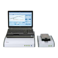
System Description
B
B
Installation
Space and Power Requirements
3.3 Space and Power Requirements
e RTCA SP Instrument is designed as a low-power consumption system with universal
power adaptability. e total power consumption of the RTCA Analyzer and RTCA SP
Station is generally less than 10 Watts.
e RTCA Analyzer must be placed in a location that allows easy access to the rear
panel On/O Power Switch.
Do not place anything within 10 cm of the side ventilation ports of the RTCA Analyzer.
Failure to observe this may result in overheating of the equipment and increase the
risk of re.
To facilitate easy installation and access to the RTCA SP Station, the recommended
space requirement inside the incubator is 24.0 cm × 29.0 cm × 23.0 cm (W × D × H).
3.4 Environmental Requirements
e RTCA Analyzer is designed to be used in a standard laboratory environment, and the
RTCA SP Station is designed to be used in a tissue/cell culturing incubator with 98% maximum
humidity without condensation or in a standard laboratory environment. Failure to follow the
environmental requirements may reduce the operating life or cause damage to the instruments.
Do not place the RTCA Analyzer on top of a cell culture incubator.
Please avoid to install the RTCA SP Instrument in direct vicinity of other laboratory
devices which may in uence the highly sensitive electronic readout of the RTCA SP
Instrument (e.g., ultra-centrifuges, autoclaves).
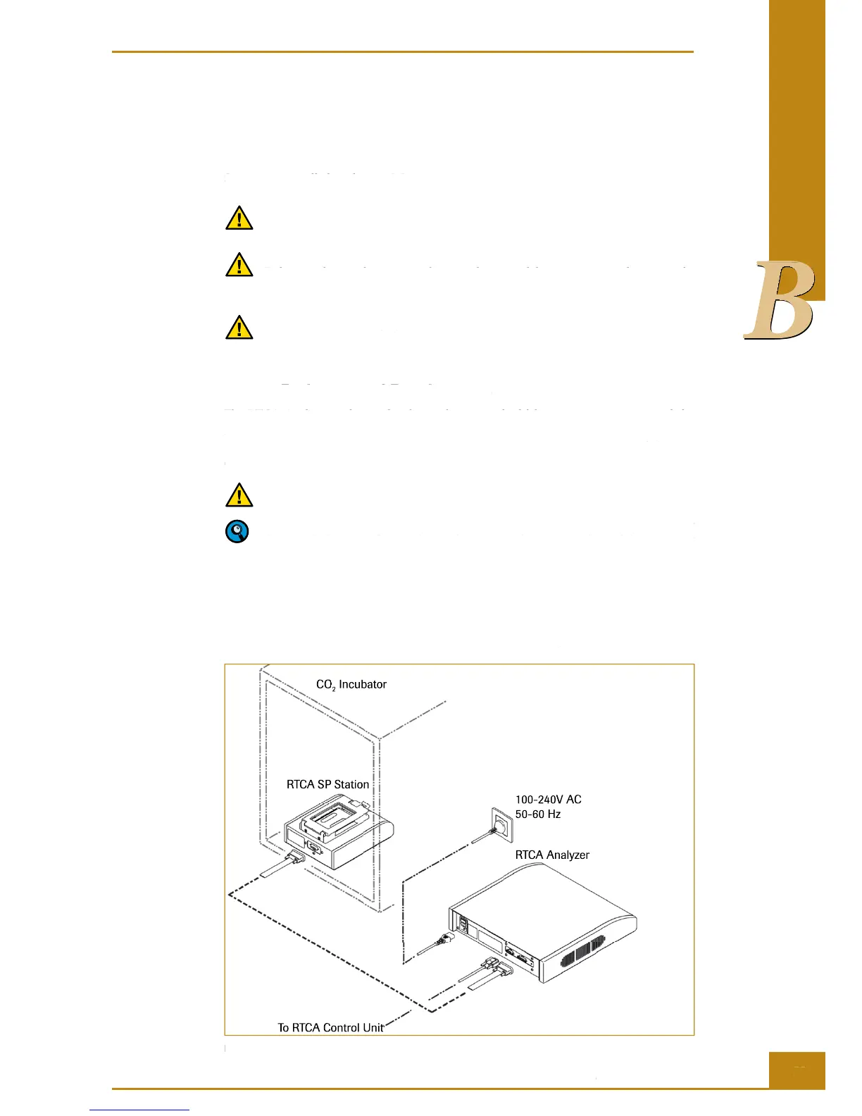
3.5 Installation of the RTCA SP Instrument
is chapter describes the installation of the RTCA SP Instrument. A schematic
presentation showing how to connect each component is provided in Figure 15.
CO
2
Incubator
100-240V AC
50-60 Hz
RTCA Analyzer
RTCA SP Station
To RTCA Control Unit
Figure 15: RTCA SP Instrument installation diagram.