3-20 Machine Maintenance Procedures
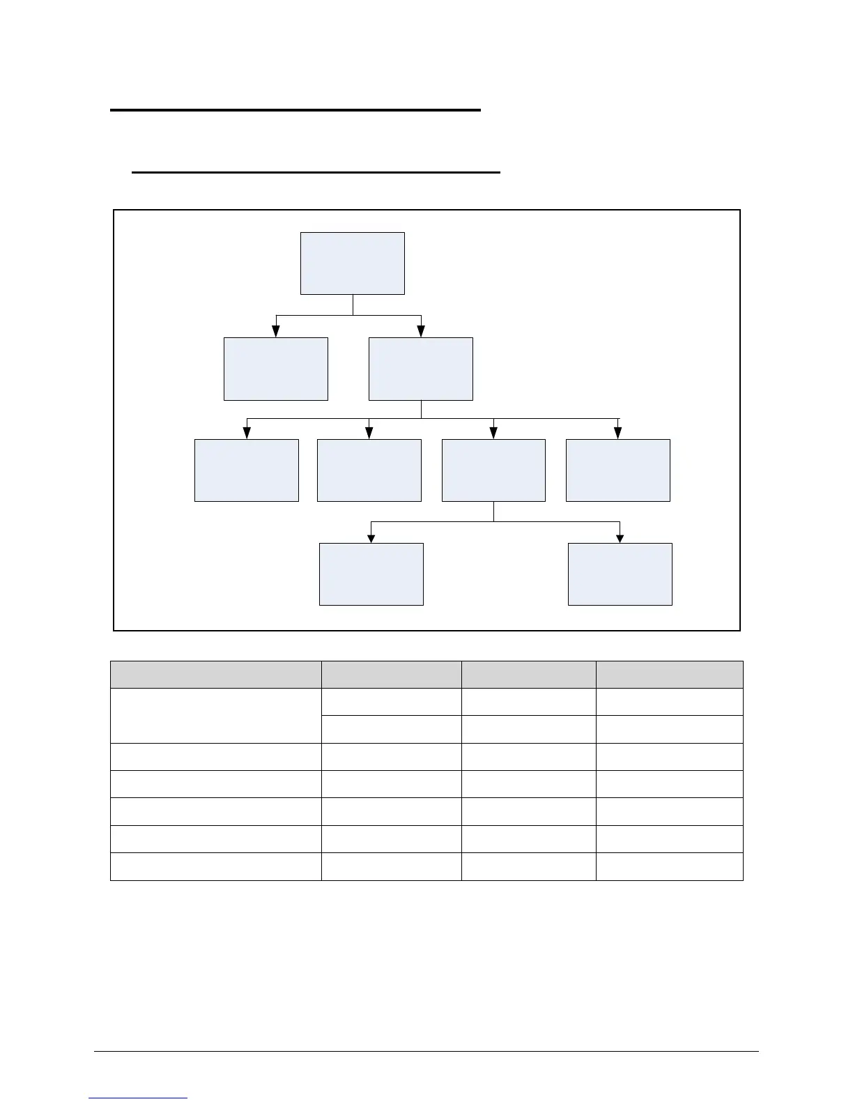
Main Unit Disassembly Process 0
Main Unit Disassembly Flowchart 0
Table 3-3. Screw List
Step Size Quantity Acer Part No.
Upper Case Removal M2.5*6 15 86.A08V7.004
M2*3 5 86.SA107.001
IO Board Removal M2.5*4 1 86.A08V7.014
Mainboard Removal M2.5*4 2 86.A08V7.014
Speaker Removal M2*2 4 86.W4107.002
LCD Module Removal M2.5*6 3 86.A08V7.004
Support Bracket Removal M2.5*4 4 86.A08V7.014
Upper Case
LCD
Module
MainboardIO Board
RTC
Battery
Support
Bracket
Speaker
Thermal
Module
DC-in Jack