Service and Maintenance 3-29
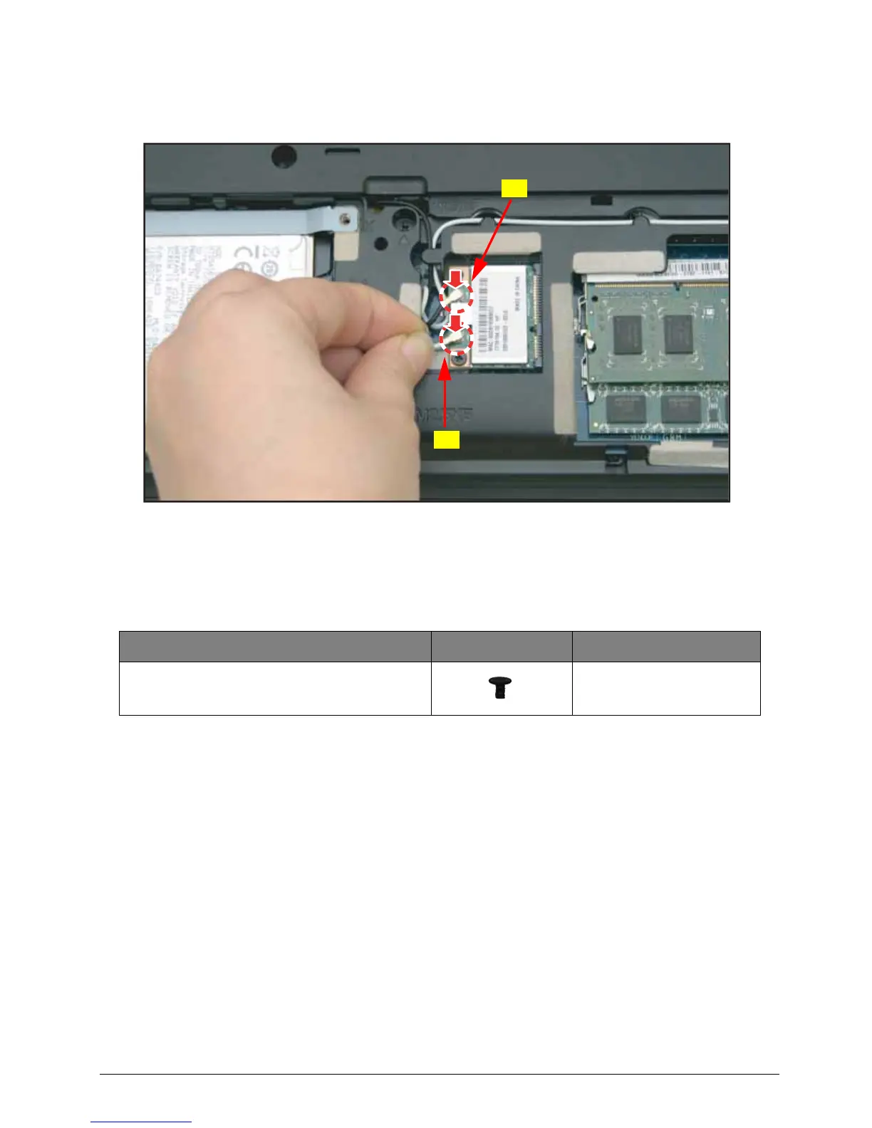
3. Connect the antenna cables to the WLAN module connectors:
• Main (A - black) antenna cable to the upper connector.
• Auxiliary (B - white) antenna cable to the lower connector.
Figure 3:37. Connecting the Antenna Cables
4. Install the base door (see Base Door Installation on page 3-13).
Table 3:7. WLAN Module Screws
Screw Name Screw Type Quantity
M 2.0 x 3.0 1