2. Proceed to the electric connection as shown:
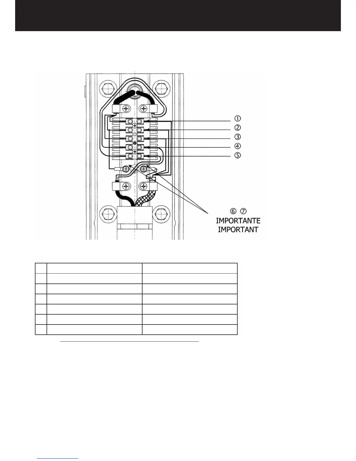
TERMINAL BOARD CONNECTION DIAGRAM
1 BROWN L = PHASE
2 YELLOW GREEN T = GROUND
3 BLUE N - NEUTRAL
4 BLACK COMMUNICATION
5 RED COMMUNICATION
6 YELLOW GREEN T = GROUND
7 YELLOW GREEN T = GROUND
THE COMMUNICATION CABLES ARE NOT POLARIZAED
3. Connect the pantograph cable shield to the grounding potential 6.
4. Connect the wall plate to the grounding potential 7.
5. Clamp the cables with the cable clamps provided.
6. Reassemble the terminal board cover.