CONNECTION INSTRUCTION TO THE TIMER
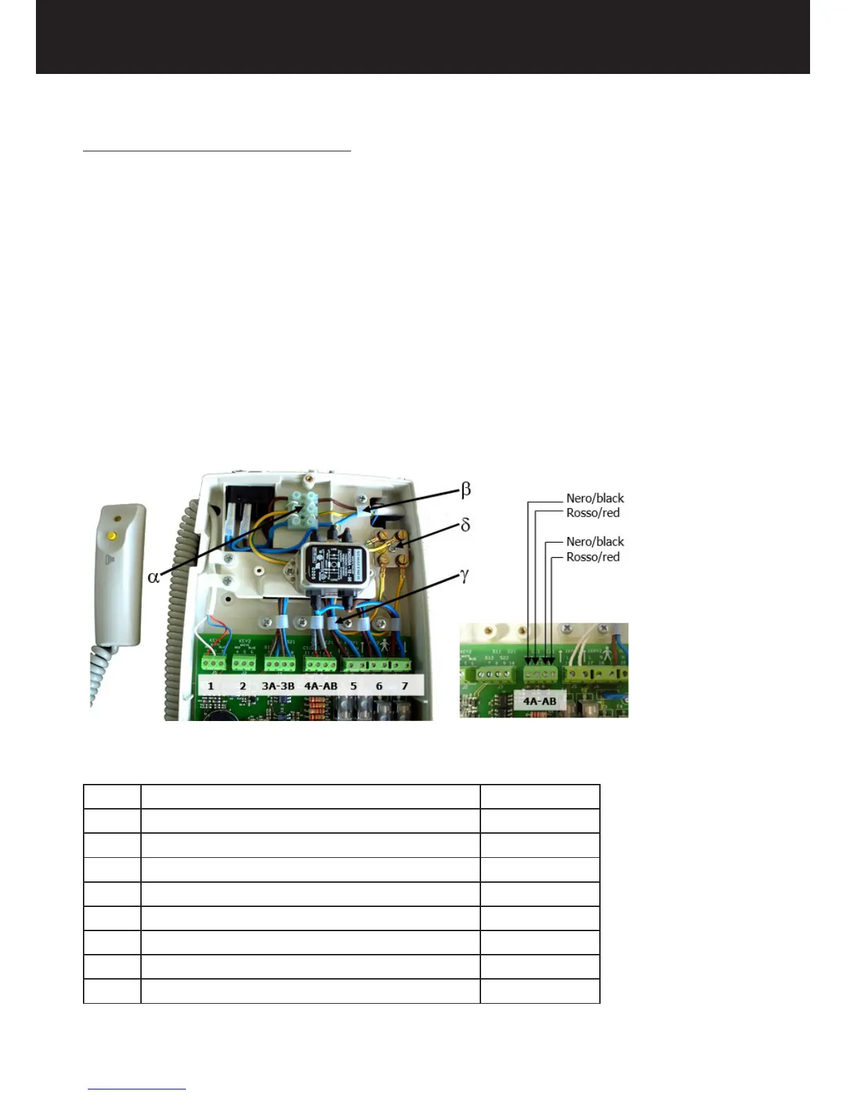
1. Connect the power supply cable to the terminal board α.
2. Insert the three mains cables into the rack.
3. Fix them with the cable clamp β.
4. Connect the cables coming from the tubehead 1 to the terminals XRAY1.
5. Connect the communications cables from the tubehead 1 to the terminals C11 and C12.
6. Connect the yellow-green grounding cable to the equipotential metal plate δ.
7. Connect the cables coming from the tubehead 2 to the terminals XRAY2.
8. Connect the communications cables from the tubehead 2 to the terminals C21 and C22.
9. Connect the yellow-green grounding cable to the equipotential metal plate δ.
10. Clamp the cables in the cable clamp γ.
11. Connect the Rx signalling lamps for external use (OPTIONAL).
12. Connect the remote control buttons (OPTIONAL).
13. Check the conguration on the dip-switches.
14. Reconnect the 26-pole connector.
15. Close the timer with the three screws.
16. Mount the sliding cover and the plug of the. wall plate
17. Reconnect the power supply.
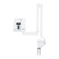
1 TUBEHEAD 1 CONTROL BUTTON
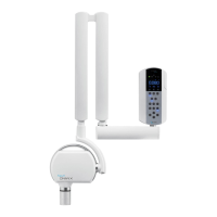
2 TUBEHEAD 2 CONTROL BUTTON OPTIONAL
3A TUBEHEAD 1 RX SIGNALLING LAMP OPTIONAL
3B TUBEHEAD 2 RX SIGNALLING LAMP OPTIONAL
4A RS232 COMMUNICATION FOR TUBEHEAD 1
4B RS232 COMMUNICATION FOR TUBEHEAD 2
5 TUBEHEAD 1 POWER SUPPLY
6 TUBEHEAD 2 POWER SUPPLY
7 TIMER POWER SUPPLY