29 ADAM-5000 Series User Manual
Chapter 3 Analog I
O Module Calibration
3.1.2 Analog Output Module Calibration
The output current of analog output modules can be calibrated by using a low calibra-
tion value and a high calibration value. The analog output modules can be configured
for one of two ranges: 0-20 mA and 4-20 mA. Since the low limit of the 0-20 mA range (0
mA) is internally an absolute reference (no power or immeasurably small power), just
two levels are needed for calibration: 4 mA and 20 mA.
1. Set the ADAM-5000 system to be INITIAL Mode then apply power to the system
including the analog output module for about 30 minutes.
2. Ensure that the module is correctly installed and is properly configured for the
range you want to calibrate. You can do this by using the ADAM utility software.
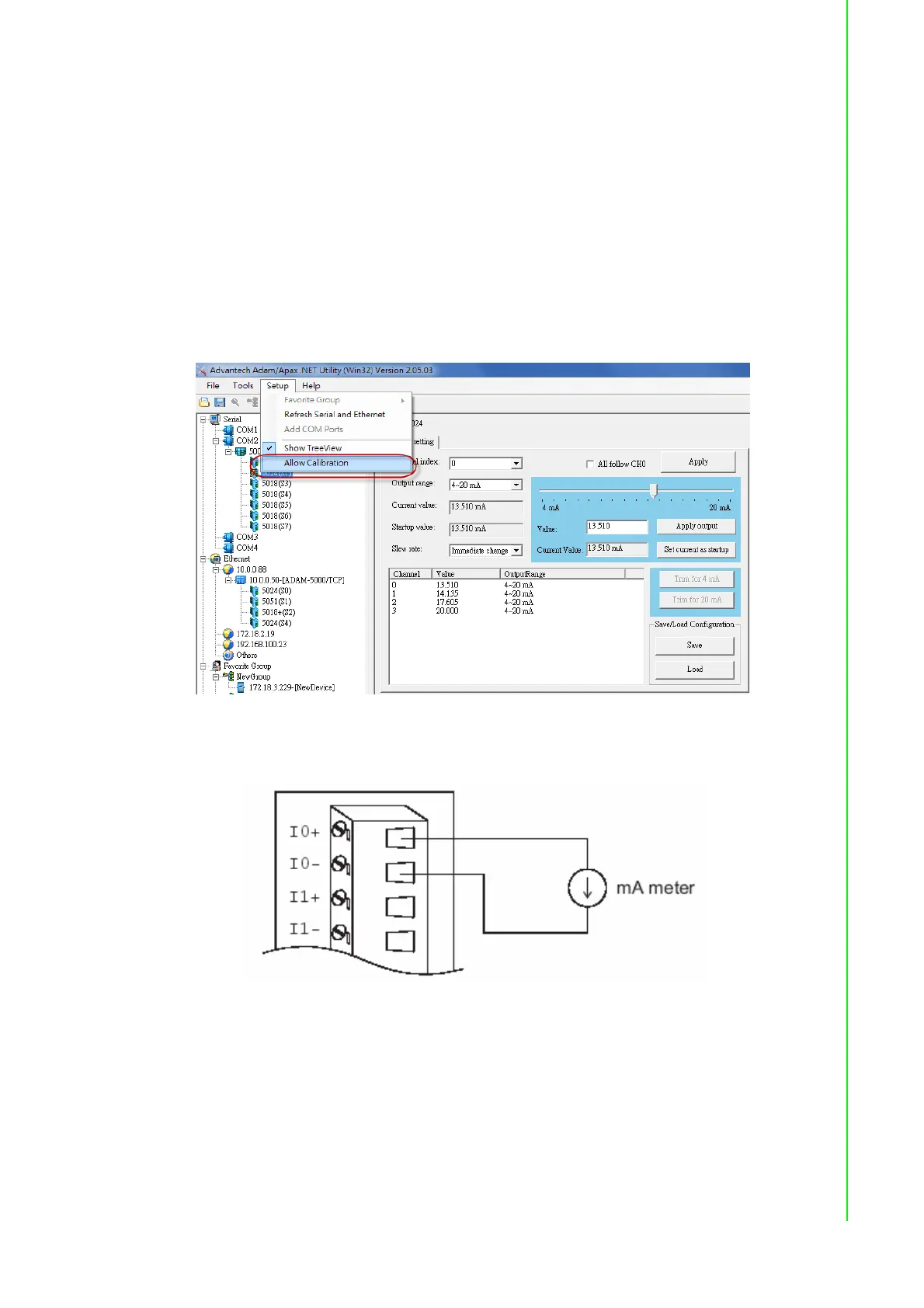
3. Before execute the calibration process in the utility, enable the calibration func-
tion by checking [Setup -> Allow Calibration ]
4. Connect either a 5-digit mA meter or voltmeter with a shunt resistor (250 ohms,
.01 % and 10 ppm) to the screw terminals of the module.
Figure 3.2 Output Module Calibration
5. Issue the Analog Data Out command to the module with an output value of 4
mA.
6. Check the actual output value at the modules terminals. If this does not equal 4
mA, use the "Trim" option in the "Calibrate" submenu to change the actual out-
put. Trim the module until the mA meter indicates exactly 4 mA, or in case of a
voltage meter with shunt resistor, the meter indicates exactly 1 V. (When calibrating
for 20 mA using a voltage meter and shunt resistor, the correct voltage should
be 5 V.)