29
EN
5.5. DIP SWITCH SETTINGS FOR MULTI SYSTEM INSTALLATIONS
if the indoor units of several MVA systems have to be managed, cer-
tain dip switches have to be set on the MASTER outdoor units of each
system (if one or more systems foresee several modules, these settings
must ONLY be performed on the Master module); The DIPs to be set
are as follow:
• SA2 = Dip to specify the address of the system in relation to the
MVACC accessory;
• SA8 = Dip to specify if the outdoor unit is Master or Slave;
The procedure to change the value of the dip switches on the outdoor
units is as follows:
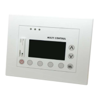
WARNING:
• In the positioning of the dipswitches, the “0” status is
represented with the Dip lever positioned up, towards
the wording “ON” as shown in the relative figure;
• The possible setting of the Dipswitches must be
done while the unit is NOT connected to the power
source;
• The system (in case of installations with several
modules) must have one MASTER while the remain-
ing modules must be set as slaves;
WARNING:
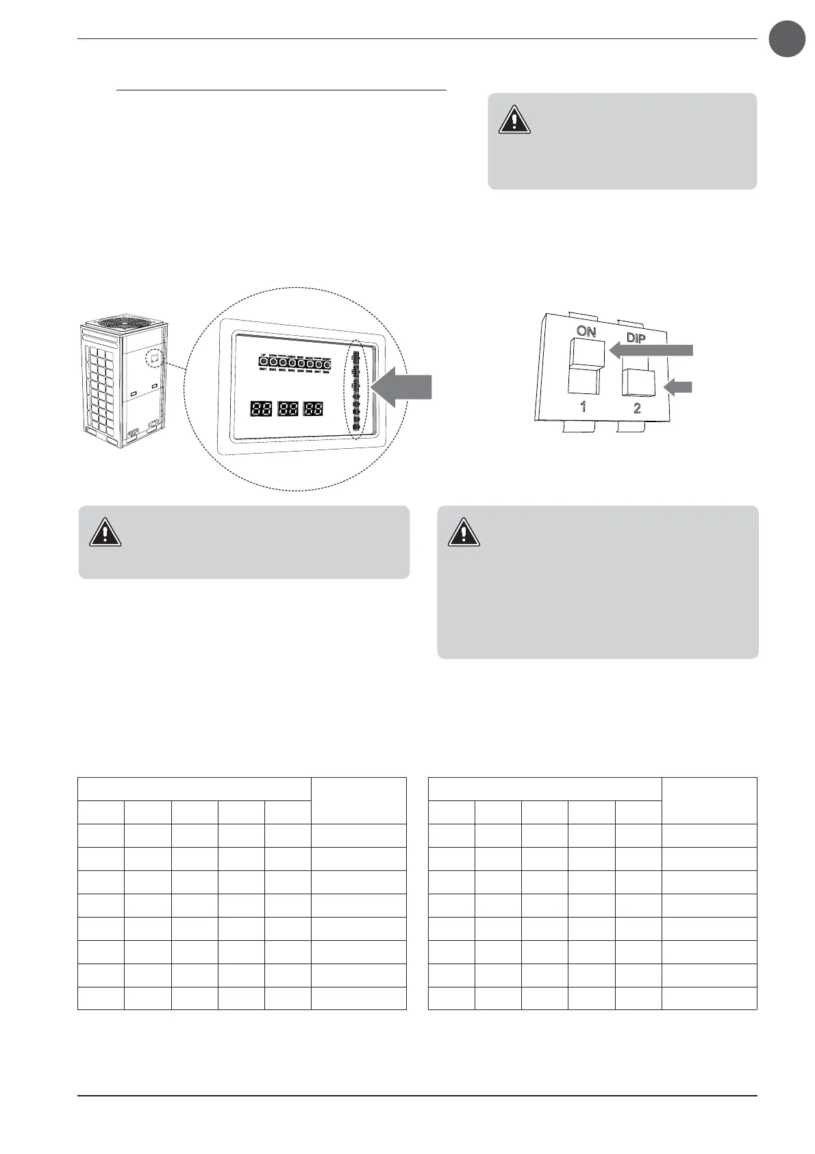
To be able to set the DipSwitch it is possible to access
through the flap located on the bulkhead that pro-
tects the electronic board of the outdoor unit.
DipSwitch
Value = 1
Value = 0
Each Master outdoor unit to be connected to the MVASZC accessory must have
a unique address from 0 to 15, where the system with address 0 will be considered
the Master system by the MVASZC accessory ; below is a table with the values to be
assigned to dip SA2 to specify the various addresses:
WARNING:
Dip SA8 should not be set but verified
only to be sure to be able to make the
connection on the Master (this check is
only necessary on MVA systems with at
least two outdoor modules)
SA2
Address
Dip1 Dip2 Dip3 Dip4 Dip5
0000/ 0
1000/ 1
0100/ 2
1100/ 3
0010/ 4
1010/ 5
0110/ 6
1110/ 7
SA2
Address
Dip1 Dip2 Dip3 Dip4 Dip5
0001/ 8
1001/ 9
0101/ 10
1101/ 11
0011/ 12
1011/ 13
0111/ 14
1111/ 15