Chapter 5: Troubleshooting
Primary Trouble Isolation
5–9
8VHWKHIROORZLQJSURFHGXUHWRWHVWWKHIURQWSDQHO/('OLJKWHPLWWLQJGLRGHLQGLFDWRUV
1 Enable the graphical interface.
2 Select Self Test from the Utilities menu.
3 Select LED from the Self Test drop-down list box, then click Start Test.
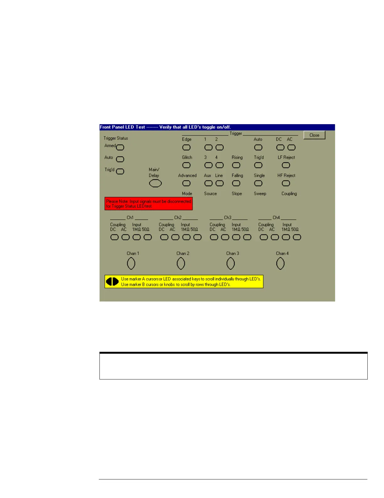
7KH/('WHVWVFUHHQDSSHDUVZKLFKVKRZVDV\PEROLFUHSUHVHQWDWLRQRIDOOIURQWSDQHO/('
LQGLFDWRUV6HHILJXUH
Figure 5-4
LED Test Screen
4 Push the Marker A left and right arrow keys to highlight each LED symbol in the test
screen. Verify that the corresponding LEDs on the front panel are the only ones
illuminated.
5 When you are finished, click Close.
If any of the LEDS do not work, go to “To check the LEDs” later in this chapter.
6 If both tests pass, go to step E.
G
Self Calibration
1 Complete a self Calibration by following the procedures in chapter 3, “Testing
Performance.”
2 If the calibration test fails, replace the acquisition assembly. If the calibration test passes,
go to step F.
H
The system is operational. Performance test the oscilloscope using the procedures in
chapter 3 of this service manual.
Test by Rows
You can use the Marker B arrow keys to test LEDs by row; however, in the event that two LED indicators
are shorted together, there is a small chance that the test will not reveal the failure.