Setting Up the 708-DS / 709-DS 3
708-DS / 709-DS Operator’s Manual 45
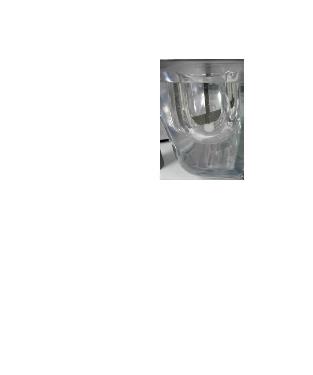
Figure 23 Inserting Height Spheres
3 Lower the drive unit to its operating position (until it stops).
4 With the shaft locking collars loosened, carefully lower each shaft
until the bottom of the paddle blade rests against the height sphere.
5 Ensure the shaft locking collar is flush against the top of the spindle
assembly by rotating each shaft until resistance is met.
6 Tighten each shaft locking collar securely.
7 Raise the drive unit to its home position.
8 Remove the height spheres from the vessels.