Installation 1
Installation and First Startup 39
4
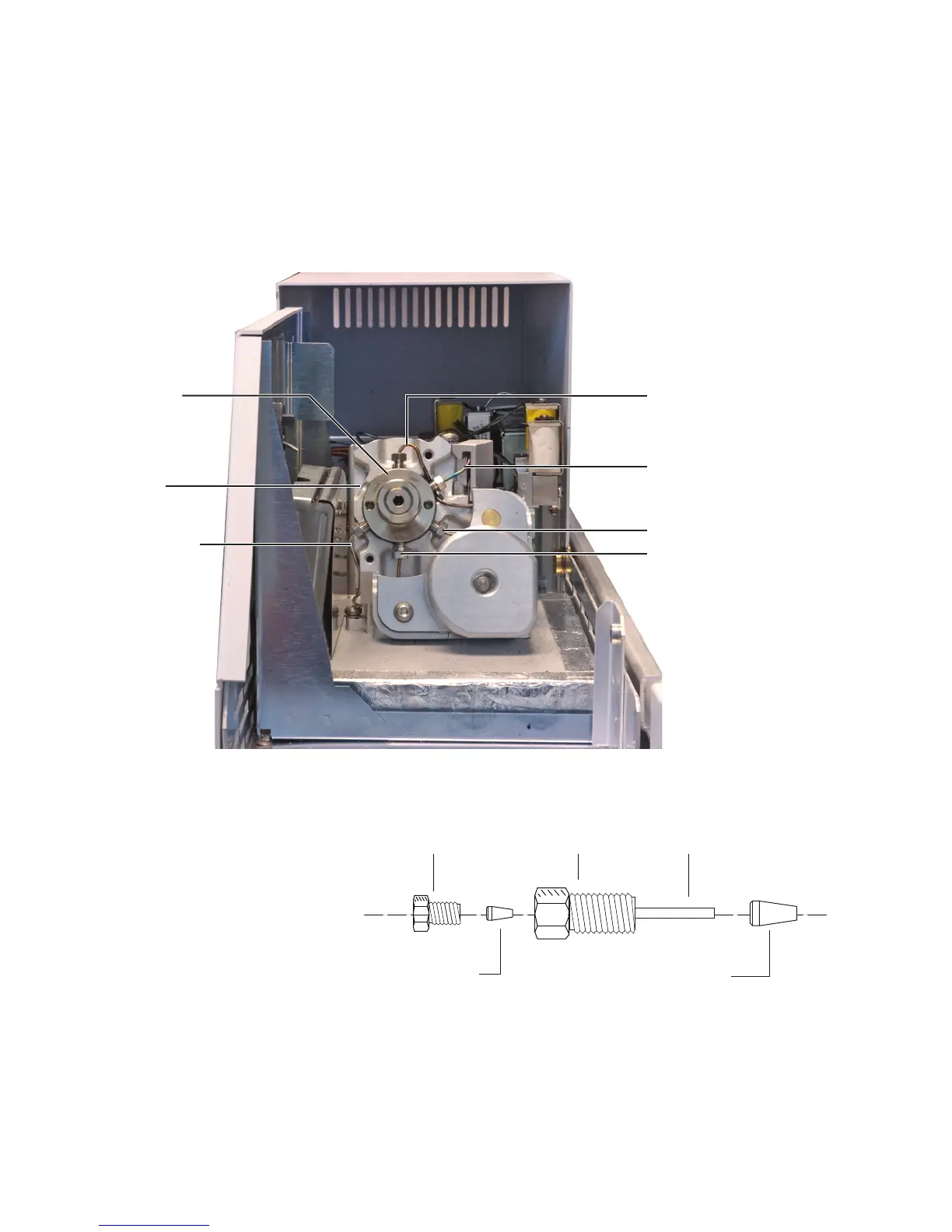
The transfer line will install in the valve port at the
10 O’clock position, as shown in the figure below (valve
port 3). Remove the 1/16- inch plug. Save the plug for
future use.
5 Disassemble the 1/16- inch internal reducer provided in
the HS ship kit.
Figure 13 Internal reducer parts
Sample loop
Sample loop
Carrier gas line
10 O’Clock
position
6 port valve
Vial pressurization gas
line
Sample probe
3/16-inch nut
Polyimide ferrule
1/4-inch nut
Stainless steel ferrule
1/16-inch tube

 Loading...


