Chapter 4 225
Key Function Descriptions
Key Descriptions
This allows amplitude correction to be entered to
compensate for changes in conversion loss with
frequency. To enter a new value, use the data keys. To
change the displayed frequency, use the step keys. Any
changes to the data also affect the mean conversion loss
stored under AVERAGE CNV LOSS. <Undefined
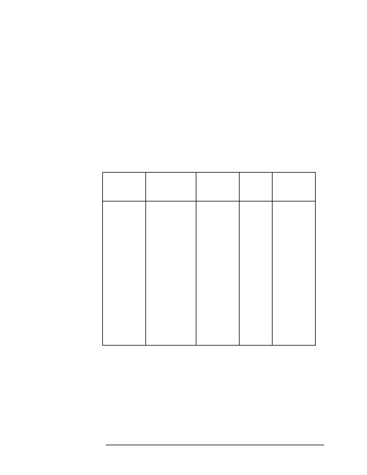
Cross-Reference> shows the number of flatness points
for each band and the default flatness values. To view
the correction, connect a 310.7 MHz signal of a known
amplitude (approximately −30 dBm)to the IF inputand
set the analyzer to sweep the associated band.
Front-panel key access:
AUX CTRL
COLOR Selects the HP PaintJet color printer (or compatible
device) for use by the
COPY key.
Front-panel key access:
CONFIG
CONFIG Accesses a menu of settings that allow information
shown on the instrument’s display to be copied to an
external GPIB printer or plotter. Under this menu, the
analyzer GPIB address can be changed and external
mixing set to preselected or unpreselected.
Table 4-5 Flatness Points and Conversion Losses for External Mixing
Bands
Frequency
Band
Frequency
Range (GHz)
Number of
Flatness
Points
Point
Spacing
Conversion
Loss
K 18.0 to 26.5 6 2 GHz 30 dB
A 26.5 to 40.0 8 2 GHz 30 dB
Q 33.0 to 50.0 7 3 GHz 30 dB
U 40.0 to 60.0 6 4 GHz 30 dB
V 50.0 to 75.0 6 5 GHz 30 dB
E 60.0 to 90.0 7 5 GHz 30 dB
W 75.0 to 110.0 8 5 GHz 30 dB
F 90.0 to 140.0 6 10 GHz 30 dB
D 110.0 to 170.0 7 10 GHz 30 dB
G 140.0 to 220.0 9 10 GHz 30 dB
Y 170.0 to 260.0 7 15 GHz 30 dB
J 220.0 to 325.0 8 15 GHz 30 dB
 Loading...

