3-19
Replacing Assemblies
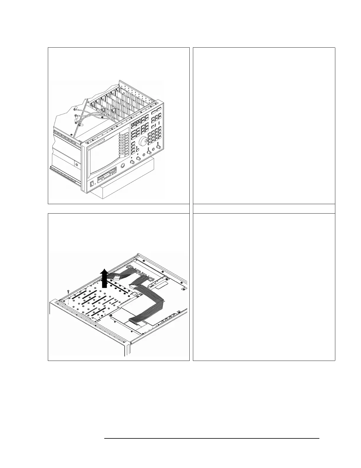
To remove analog motherboard
5
Raise the front of the analyzer off the bench by placing a
book under the analyzer’s front frame.
6
Position the motherboard cable extraction tool (from the
service kit) inside the cardnest over the coaxial cable
connector for the A35 Analog Source assembly. Carefully
lower the tool allowing the center to come up as the tool is
lowered into position. Once in position, push the center
down to push the cable out of the A91 Analog Motherboard.
Repeat for the A10 Analog Input assemblies.
7
Remove the screws from the A91 Analog Motherboard. Use
a 5 mm nut driver for 42 screws, a T-10 torx driver for 13
screws, and a T-15 torx driver for 1 screw.
8
Lift up the A91 Analog Motherboard unplugging it from the
A90 Digital Motherboard. Disconnect the power supply
cable from A91 P2 and the probe power cables from A91 P3
and P5.

 Loading...


