Service Guide N5230-90024 5-3
PNA Series Microwave Network Analyzers Theory of Operation
N5230C Network Analyzer System Operation
Network Analyzer System Operation
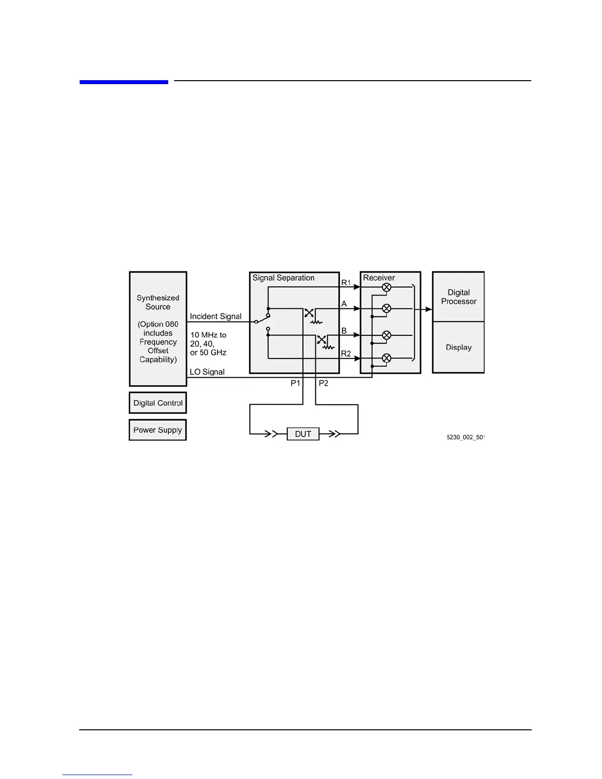
The PNA series network analyzer generates a phase-locked incident signal and an LO signal from the
internal synthesized source. By means of signal separation, the incident signal is divided into a reference
signal and a test signal.
The reference signal is applied to the receiver group, while the test signal is applied to the device under test
(DUT) and then to the receiver group. The LO signal is applied directly to the receiver group where it is mixed
with the test and reference signals to produce IF signals for each of the four channels. These IF signals are
downconverted and then sampled and digitally processed. Figure 5-1 is a simplified block diagram of the
network analyzer system.
Figure 5-1 System Simplified Block Diagram
Functional Groups of the Network Analyzer
The operation of the network analyzer can be separated into major functional groups. Each group consists of
assemblies that perform a distinct function in the instrument. Some of the assemblies are related to more
than one group, and all of the groups, to some extent, are interrelated and affect each other's performance.
The major functional groups are:
• Synthesized Source Group
• Signal Separation Group
• Receiver Group
• Digital Processor and Digital Control Group
• Power Supply Group

 Loading...


