Service Guide N5230-90024 7-5
PNA Series Microwave Network Analyzers Repair and Replacement Procedures
N5230C Removal and Replacement Procedures
Removal and Replacement Procedures
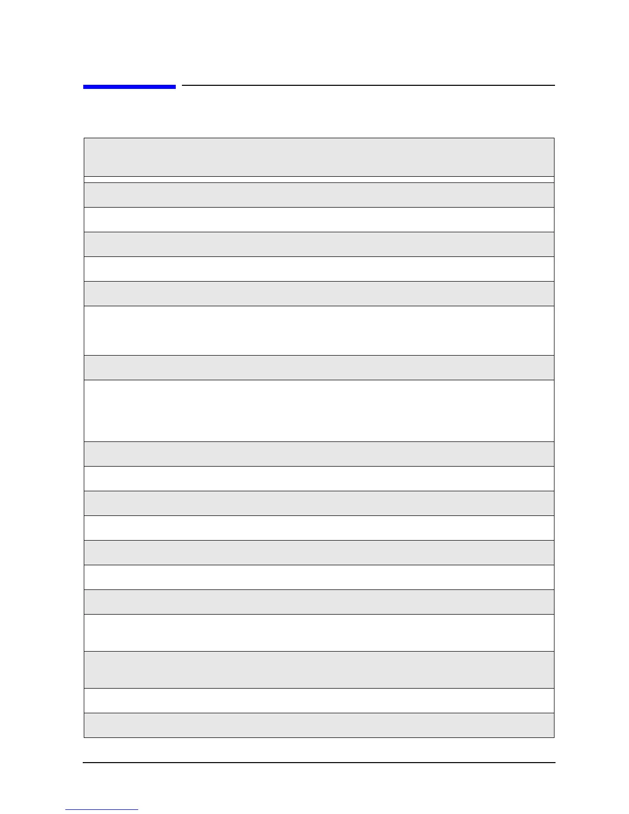
Table 7-1 List of Procedures
Reference
Designator
Assembly Description Location
N/A USB hub (part of A16 test set motherboard procedure) Page 7-24
N/A Covers, outer and inner Page 7-6
N/A Midweb and fans
Page 7-48
N/A Front panel assembly Page 7-8
N/A Battery Page 7-52
A1
A2
A3
Keypad assembly
Display assembly
Front panel interface board
Page 7-10
A4 Power supply assembly Page 7-14
A5
A6, A8
A7, A9
A10
SPAM board
Multiplier boards
Fractional-N synthesizer boards
Frequency reference board
Page 7-16
A14 System motherboard Page 7-18
A15 CPU board Page 7-20
A16 Test set m oth erbo a rd Page 7-24
A17 MASS 26.5 Page 7-26
A18 MA 26.5 Page 7-28
A19 MASS 50 Page 7-30
A20 Mixer brick
Page 7-32
A21
A22
Test po rt 1 cou pler
Test po rt 2 cou pler
Page 7-36
A25
A26
Port 1 60-dB source step attenuator (Option 1E1)
Port 2 60-dB source step attenuator (Option 1E1)
Page 7-38
A40 Not used.
A41
Hard disk drive
Page 7-40

 Loading...


