Service Guide N5230-90024 5-15
PNA Series Microwave Network Analyzers Theory of Operation
N5230C Signal Separation Group Operation
Signal Separation Group Operation
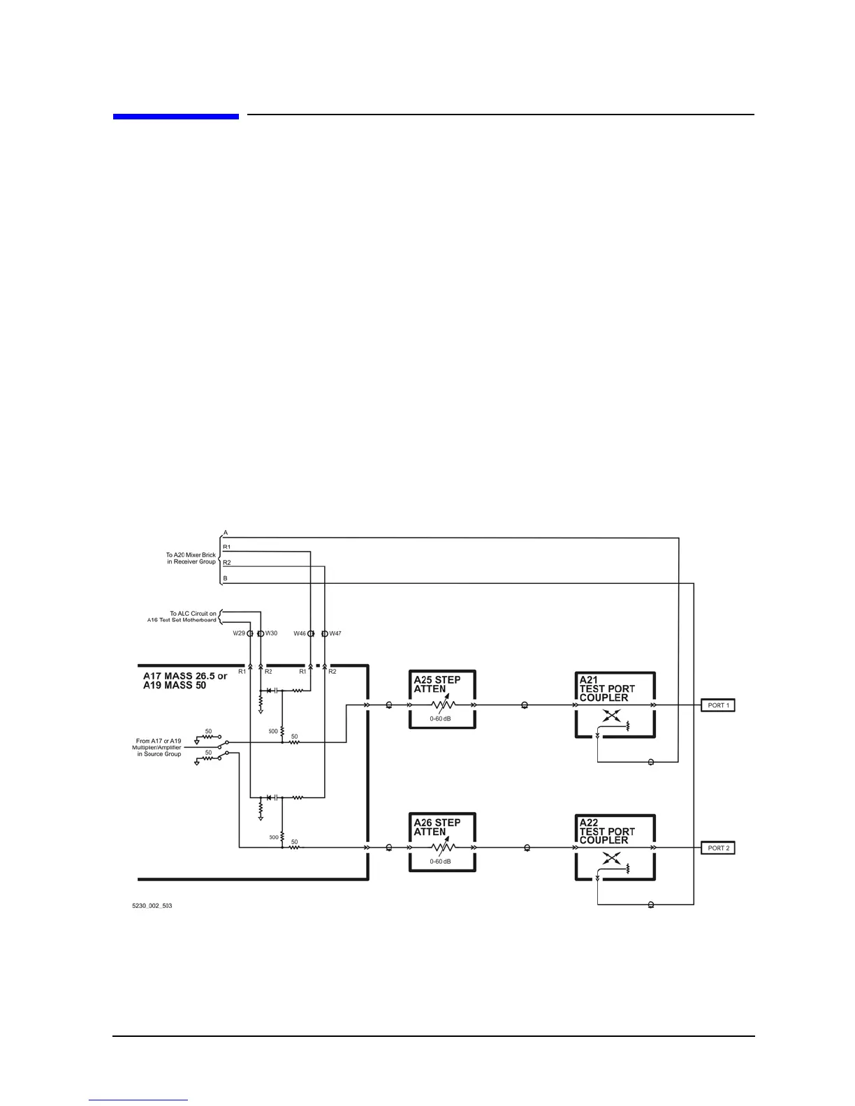
The signal separation group divides the source incident signal into a reference path and a test path. Refer to
Figure 5-3 on page 5-15.
• The reference signal is transmitted to the receiver group as the R1 and R2 inputs.
• The test signal is transmitted through—and reflected from—the device under test (DUT) and then is
transmitted to the receiver group as the A and B inputs.
• Control lines to this group are routed from the A16 test set motherboard.
In this section, the following assemblies are described:
• A17 Multiplier/Amplifier/Switch/Splitter 26.5 (MASS 26.5)
• A19 Multiplier/Amplifier/Switch/Splitter 50 (MASS 50)
• A21 and A22 Test Port Couplers
• A25 and A26 60-dB Source Step Attenuators (Option 1E1)
• Front Panel Jumpers—Configurable Test Set (Option 014)
Figure 5-3 Standard Test Set Configuration

 Loading...


